3D Printing Tolerances Explained: How to Design Parts That Actually Fit
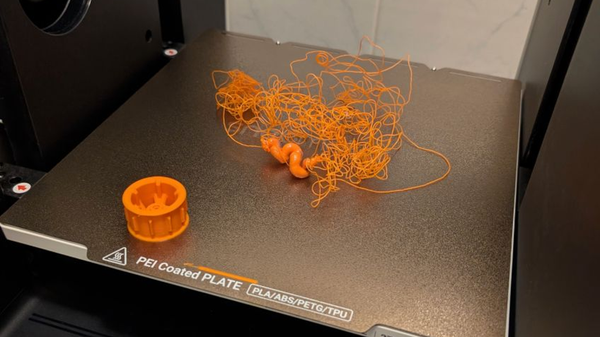
It is a uniquely frustrating experience: you spend hours designing a multi-part assembly in CAD, wait 12 hours for the print to finish, and then discover the pieces don’t fit together. The peg is too thick for the hole, the hinge won't move, or the snap-fit joint simply refuses to snap.
When this happens, the culprit is almost always a misunderstanding of tolerances.
In the digital world of your CAD software, dimensions are perfect. In the real world, physics takes over. Hot plastic shrinks as it cools, layers squish, and mechanical vibrations introduce microscopic shifts. Tolerances are the deliberate gaps you design into your digital model to account for these physical realities.
Here is exactly how to calculate and design your 3D printing tolerances so your parts fit perfectly on the first try.
What Are Tolerances in 3D Printing?
Before adjusting your designs, it helps to understand the vocabulary engineers use to describe dimensional variations.
Accuracy vs. Precision vs. Tolerance
These three terms are often used interchangeably, but they mean very different things in 3D printing (a distinction well-documented in scientific research on baseline accuracy and precision in additive manufacturing):
- Accuracy: How close your final printed part is to the exact dimensions of your 3D model.
- Precision: How consistently your printer can reproduce that exact same result, print after print.
- Tolerance: The acceptable range of dimensional deviation you design into a part so that it still functions as intended.
Why 3D Printed Parts Rarely Match the CAD File
No 3D printer creates a mathematically perfect replica of a digital file. This is due to a combination of material physics and mechanical movement.
When plastic filament is heated and extruded, it expands. As it cools on the build plate, it contracts. Furthermore, as the printhead moves rapidly, it creates mechanical resonance. Mitigating this vibration is a major focus in modern printer engineering. For example, advanced CoreXY printers like the Snapmaker U1 utilize rigid carbon fiber X-axis rails paired with Input Shaping—a vibration compensation algorithm that pre-processes movement commands to cancel out resonant frequencies. This prevents surface artifacts like ghosting and keeps dimensional deviations to an absolute minimum, even at speeds of 500mm/s.
Standard 3D Printing Tolerances by Technology
There is no universal tolerance number. The baseline accuracy of your print depends heavily on the type of 3D printing technology you are using.
FDM (Fused Deposition Modeling) Tolerances
FDM is the most common desktop 3D printing method. Because it relies on melting thermoplastic filament and layering it, it is the most susceptible to shrinkage and layer squish.
- Standard Tolerance: ±0.15 mm to ±0.5 mm
- Best For: Functional prototypes, brackets, and low-cost structural parts.
SLA (Stereolithography) Tolerances
SLA uses a UV laser or screen to cure liquid resin. Because it doesn't involve melting and cooling plastic through a nozzle, it offers significantly tighter tolerances compared to FDM.
- Standard Tolerance: ±0.05 mm to ±0.15 mm
- Best For: High-detail miniatures, jewelry molds, and precise mechanical components.
SLS (Selective Laser Sintering) Tolerances
SLS uses a laser to fuse powdered material (usually nylon). Because the un-sintered powder supports the printed part, there are no support structures to remove, resulting in excellent dimensional uniformity.
- Standard Tolerance: ±0.3 mm
- Best For: Complex geometries, moving parts printed in place, and durable end-use parts.
Designing for Assembly: 3D Printing Fit Tolerances (in mm)
When designing parts that need to connect, you must build intentional gaps—or "clearances"—into your CAD file. For FDM printing, use the following guidelines based on the type of mechanical fit you need.
Clearance Fits (Loose and Moving Parts)
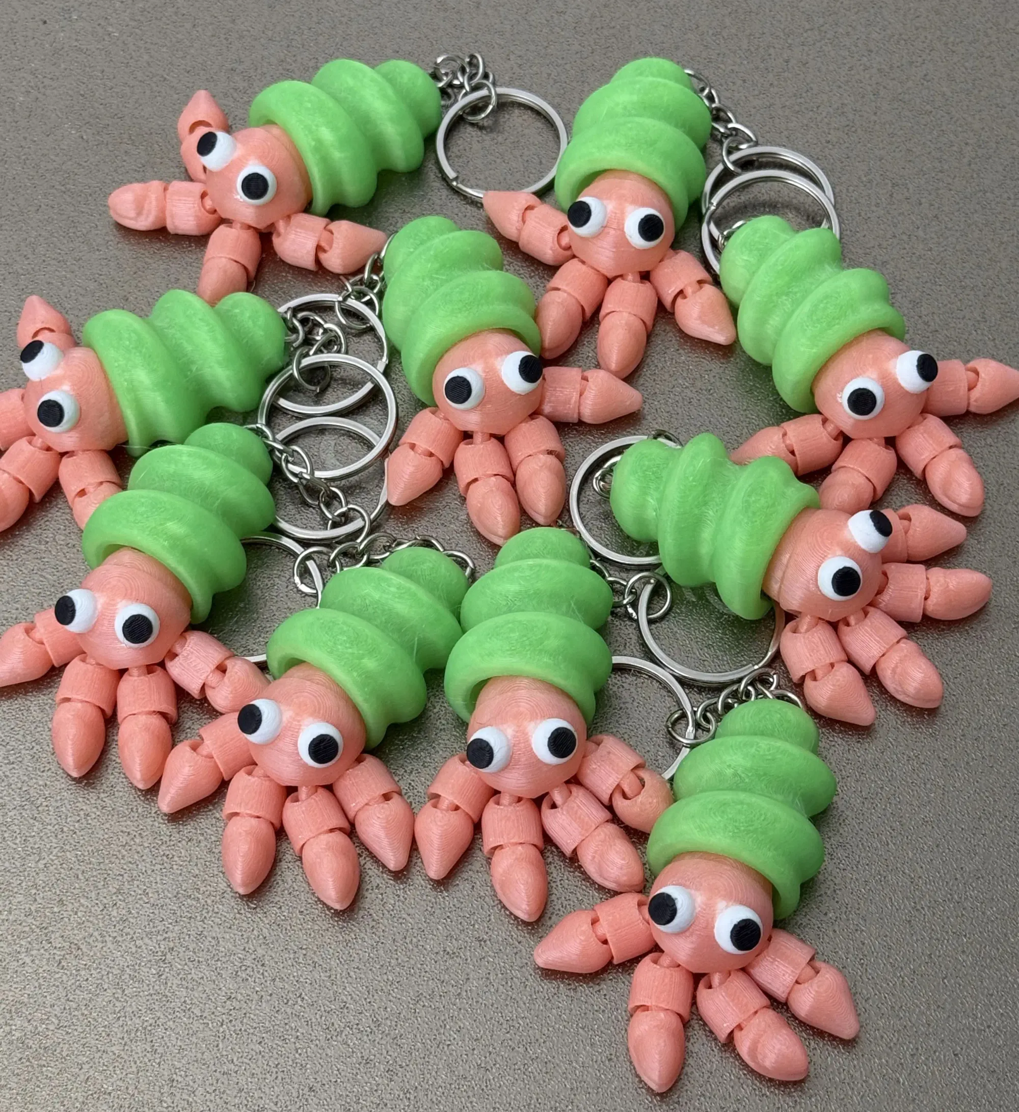
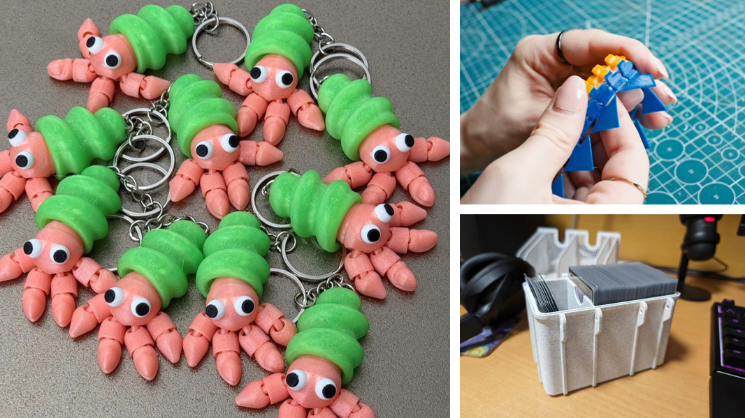
A clearance fit is used when parts need to slide, rotate, or move freely against one another. This is the standard fit for print-in-place hinges, sliding rails, or simple box lids.
- Recommended Gap: 0.3 mm to 0.5 mm
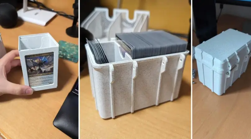
Transition Fits (Snug, Locational Assembly)
A transition fit is used when parts need to slide together with slight friction. They hold their position but can be pulled apart by hand. This is ideal for alignment pegs, interlocking static parts, and tight-fitting lids.
- Recommended Gap: 0.1 mm to 0.2 mm
Interference Fits (Press-Fit, Friction Holding)
An interference fit is used when two parts are meant to be permanently joined by force. The peg is actually designed to be slightly larger than the hole, relying on the slight flexibility of the plastic to grip tightly. This is used for threaded inserts or permanent snap-fits.
- Recommended Gap: 0.0 mm to -0.05 mm (Intentional overlap)
Best Practices for Dialing In Your Printer's Precision
Knowing the numbers is only half the battle. To guarantee success, you need to calibrate your FDM printer and material.
Print a Tolerance Test Gauge
Before committing to a 20-hour print, download a free tolerance coin or calibration cube from a repository like Printables. These small, fast-printing tools feature multiple pegs and holes with varying gaps (from 0.1 mm to 0.5 mm). Printing one will show you exactly what clearance your specific filament and printer require today.
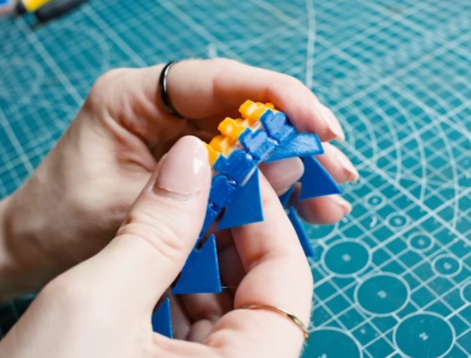
Automate and Calibrate Extrusion
When printing complex assemblies—especially multi-material or multi-color parts—extrusion flow rate consistency is critical. Inconsistent flow leads to blobs in corners, which instantly ruin tight transition fits. Modern machines handle this through smart calibration. The Snapmaker U1 uses Pressure Advance to stay ahead of flow delays during sharp corners, and its SnapSwap™ toolhead system automatically calibrates nozzle offsets to under 0.04mm. This ensures that even when swapping between four different toolheads, your structural alignments remain perfectly sharp.
Adjusting Horizontal Expansion in Your Slicer
If you download a file that doesn't fit, you don't necessarily have to remodel it. In slicers like Cura, PrusaSlicer, or Snapmaker Orca, look for the "Horizontal Expansion" or "XY Size Compensation" setting. Entering a negative value (e.g., -0.1 mm) will shrink the outer perimeters slightly and widen holes, providing extra clearance without touching the CAD data.
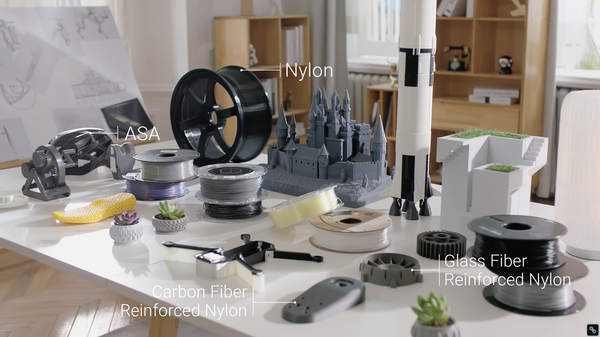
Account for Material Shrinkage
Finally, remember that not all plastics behave the same way. PLA and PETG are dimensionally stable and rarely warp. ABS and Nylon, however, shrink significantly as they cool. If you are printing a precise mechanical part and choosing ABS instead of PLA, you will often need to scale the entire model up uniformly by 1% to 2% in your slicer to compensate for the expected thermal contraction.
FAQ on 3D Printing Tolerances
How precise can 3D printing be?
Precision depends heavily on the printing technology. Resin (SLA) printers can achieve precision down to ±0.01 mm, while standard desktop FDM (filament) printers usually sit around ±0.15 mm.
What does a 1% tolerance mean in 3D printing?
A 1% tolerance means the final printed part may deviate in size by 1% of its total intended dimension. For example, if a part is designed to be 100mm long, a 1% tolerance means the acceptable final print can be anywhere between 99mm and 101mm.
What are the 4 types of tolerance?
In mechanical design and drafting, the four primary types of tolerances are Limit tolerances, Bilateral tolerances, Unilateral tolerances, and Geometric Dimensioning and Tolerancing (GD&T).
Why are tolerances important in 3D printing?
Because 3D printing uses heat and physical extrusion, materials inevitably warp, shrink, and expand. Tolerances ensure that multi-part assemblies can still function, slide, and fit together perfectly despite these microscopic physical deviations.