Guide to Designing and 3D Printing Threads
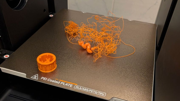
There are few things in 3D printing more satisfying than creating a multi-part assembly that fits together perfectly. And few things are more frustrating than spending hours on a print only to find that the nut and bolt you designed have fused into a single, useless piece of plastic.
If you’ve struggled to get functional, smooth-turning threads straight off your print bed, you’re not alone. The truth is that success has less to do with your printer and more to do with your design. This guide will walk you through the core principles for designing and 3D printing reliable threads, moving you from frustration to success.
Why Most 3D Printed Threads Fail
The heart of the issue isn't a flaw in your printer, but a reality of physics. When you print a 3 mm hole and a 3 mm peg, they will never fit. The extruded plastic is slightly wider than the nozzle diameter, and this "squish" closes small gaps, leading to parts that seize up. The solution is to plan for this from the very beginning.
Understanding Tolerance: The Key to a Perfect Fit
In engineering, tolerance is the planned gap you intentionally design between parts to account for real-world manufacturing variations. Think of a drawer in a cabinet; it needs a small gap on all sides to slide smoothly. Without that gap, it would jam. For 3D printing, we must design a functional clearance to ensure our threaded parts can move freely. This is the single most important concept for getting functional threads.
Core Principles for Designing Printable Threads
You can achieve reliable results in any CAD software by following these foundational principles.
Always Model the Physical Geometry
Many CAD programs offer a "cosmetic" thread option, which simply applies a visual texture to a cylinder. This looks like a thread on your screen but won't exist in the exported STL file. For 3D printing, you must ensure the threads are part of the actual 3D model's geometry. In software like Autodesk Fusion 360, this often means checking a box labeled "Modeled."
Engineer the Clearance with an Offset
This is how you create the functional clearance, or tolerance. The most reliable method is to design the male (external) and female (internal) threads to their correct size, and then slightly shrink the male thread. This is done by applying a small negative offset.
Choose a Print-Friendly Thread Profile
Not all thread shapes are created equal, especially for FDM printing. Standard V-shaped threads have sharp, 60° angles that can be difficult to print accurately as overhangs. A much better option is an ACME or trapezoidal thread. Their flatter, squared-off shape is more stable to build layer-by-layer and results in a stronger, smoother-operating connection. Most CAD programs will allow you to select this as a profile type.
Add a Chamfer for Easy Assembly
A simple but critical design choice is to add a chamfer (a small 45° angled cut) to the leading edge of your screw and the opening of your nut. A chamfer acts as a guide, making it significantly easier to align and start engaging the threads. It also removes the fragile, paper-thin starting point of the helix, which often prints poorly and can break off.
Always Print a Test Piece
Every printer, material, and slicer profile is a unique combination. Before you commit to printing a large, complex part, take five minutes to design a simple M10 or M12 nut and bolt test. Printing a small test piece allows you to quickly verify if your chosen offset works with your specific setup, saving you hours of time and kilograms of filament.
From Digital to Physical: Slicer Principles for Clean Threads
A great design can still be let down by poor slicer settings. Follow these principles to give your model the best chance of success.
The Principle of Orientation: Go Vertical
For maximum accuracy, always orient your threaded parts to be standing up on the build plate. Printing threads vertically ensures they remain perfectly circular. Laying them on their side squashes the profile into an oval shape and requires messy, hard-to-remove supports.
The Principle of Precision: Fine Layer Heights
Threads are composed of fine, curving details. A smaller layer height allows your printer to reproduce that curve more accurately. For clean threads, use a layer height of 0.16 mm or, even better, 0.12 mm. The extra print time is well worth the massive improvement in quality.
The Principle of Strength: Use More Perimeters
For thread strength, the number of perimeters (also called walls or shells) is far more important than the infill percentage. The perimeters form the solid outer surfaces where the threads are located. A higher wall count ensures that the threads are carved from solid plastic, not a thin shell. A minimum of 3 to 4 perimeters is strongly recommended to prevent threads from breaking or stripping easily.
The Right Tool for the Job: Printed Threads vs. Metal Inserts
While you can 3D print threads for almost anything, sometimes it isn't the best solution. Knowing when to use an alternative is a key skill for any maker.
When to Use Printed Threads
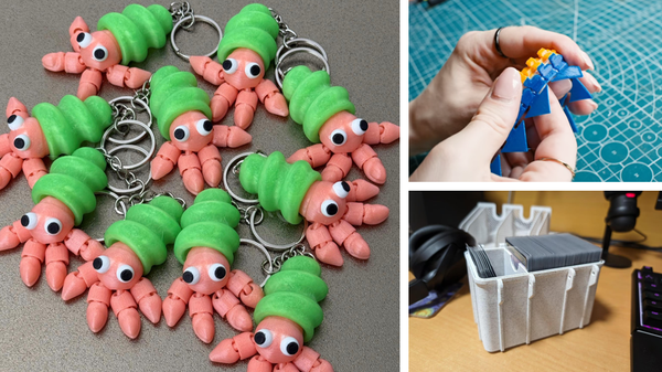
Fully 3D printed threads are excellent for applications where the connection won't be under immense stress. They are ideal for projects like container lids, workshop jigs, and other non-structural parts. This is also where material choice is critical. While a material like PLA has high tensile strength, it’s also very brittle and can snap under the twisting force (torsion) of being tightened. For functional screws, a tougher material like PETG or ABS is often a better choice, as it's more forgiving and less likely to crack.
A Stronger Alternative: Heat-Set Threaded Inserts
For parts that require high strength or need to be assembled and disassembled repeatedly, the professional solution is to use a metal heat-set insert. These are small brass cylinders with machine threads on the inside and special fins on the outside. You simply use a soldering iron to press the insert into a 3D printed hole, melting the surrounding plastic and creating an incredibly strong, durable, and reusable mechanical bond.
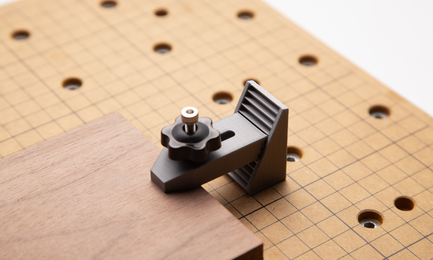
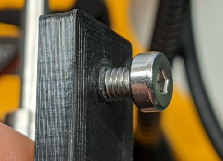
This 3D printed CNC fixture, a great example of custom jigs and fixtures, uses a metal bolt and knob to provide reliable clamping force far greater than a plastic thread could handle.
Go Forth and Experiment
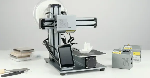
Printing functional threads is a gateway skill in 3D printing. It opens up a new world of complex, functional, and practical designs—a capability that a versatile machine like the Artisan 3-in-1 puts directly into your hands. By understanding the core principles of design, slicing, and material choice, you can move past guesswork and start creating parts that work together, straight off the print bed, every single time.