Milling Chess Pieces
Using the Snapmaker Rotary Module and Rest Machining with Fusion 360
By Dominik Bilitewski
1. Project presentation and motivation
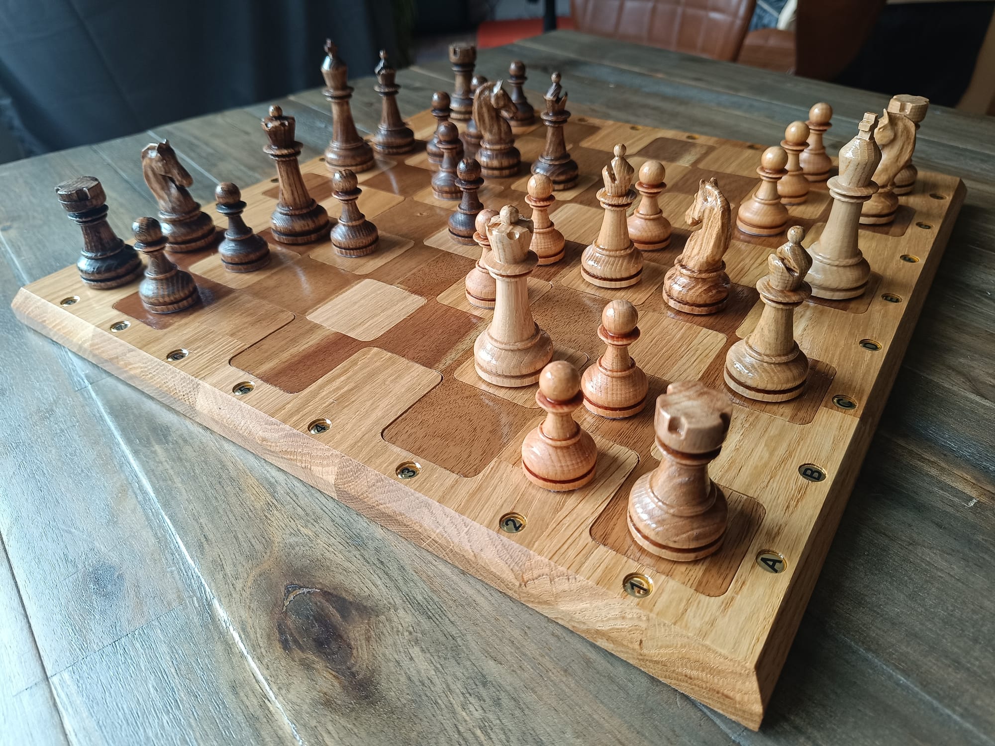
Although I have never played chess in my life, I have always been fascinated by the game itself, but above all by the aesthetics of the chess pieces. A high-quality chess set made of wood simply exudes a certain timeless elegance. Unfortunately, all the manufacturers of affordable wooden sets use knight pieces that are strangely abstract or only roughly carved, in my opinion. So I had no choice but to buy the rotation module for my Snapmaker Artisan and set out to make my own set.
To shorten your journey a little, I have taken the trouble to document mine for you below. I will only discuss the pieces here, as the production of the board should not be difficult for beginners with a little research. Beginners like I was when I started this project. In fact, before purchasing the Artisan, I had never worked with a CNC milling machine or wood in general, so the experts among you are welcome to optimize my processes.
2. Preparing the rotation module
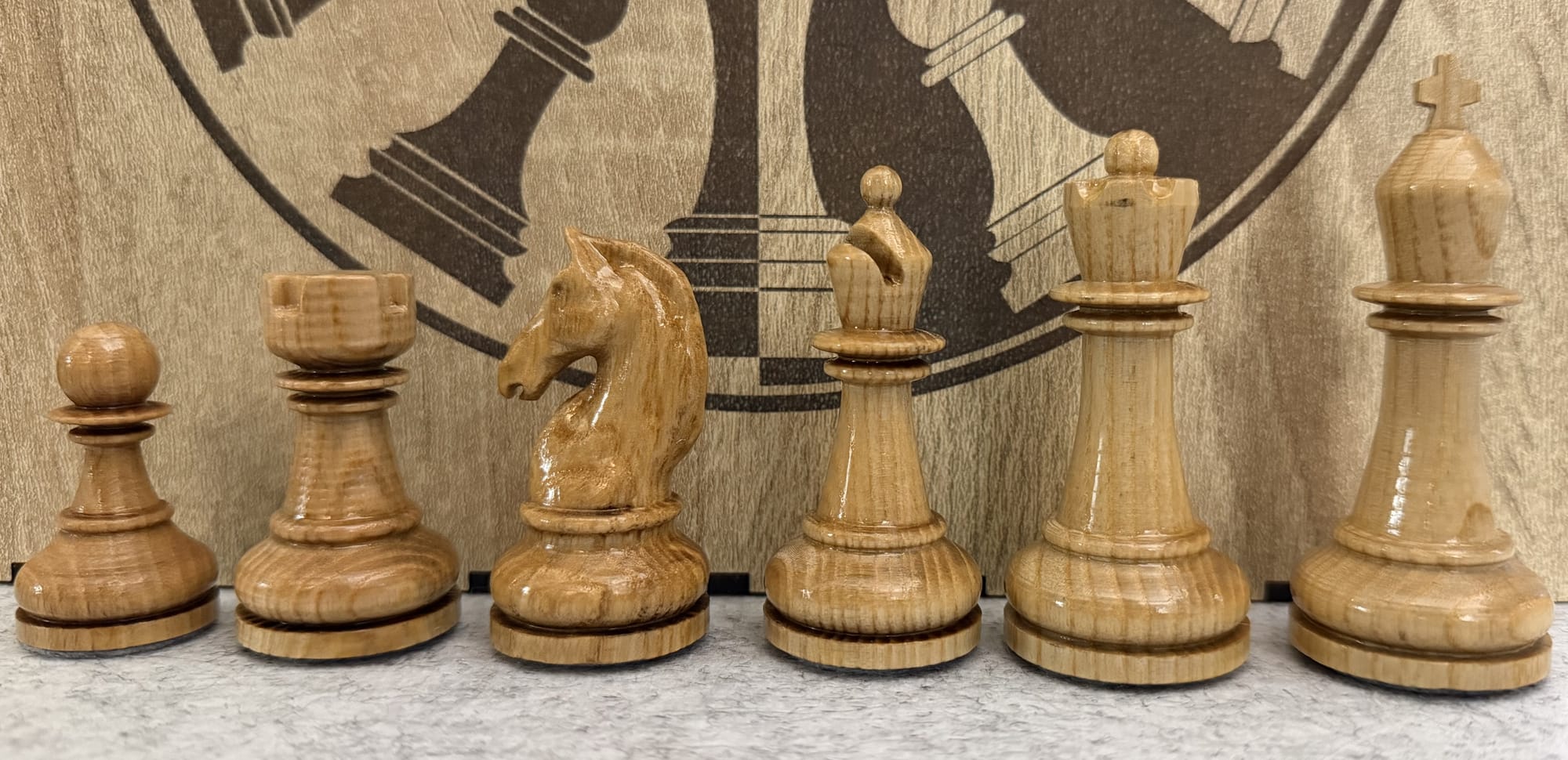
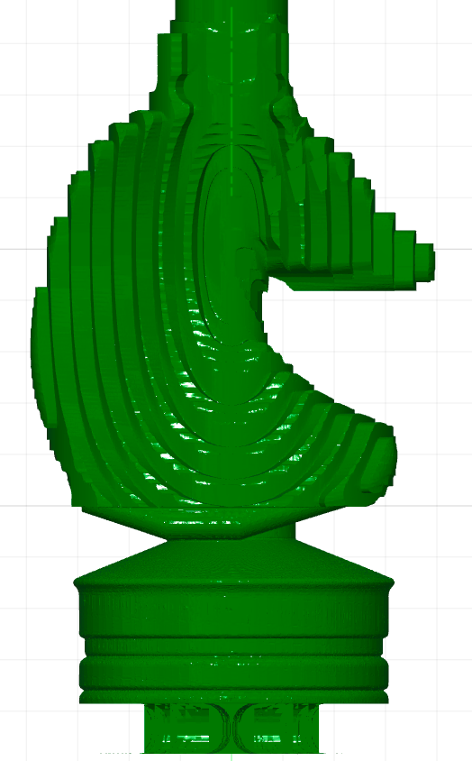
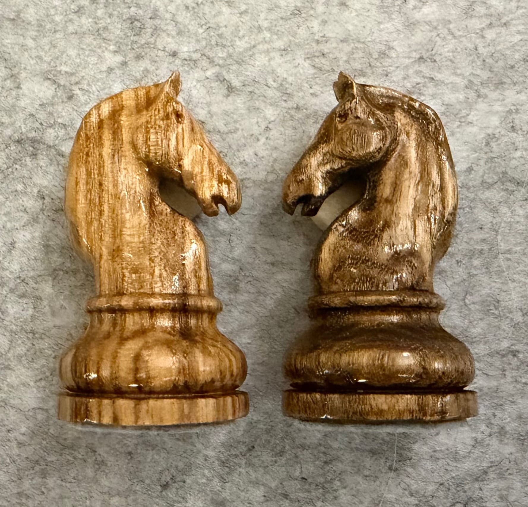
When you look at the horse from my set, you immediately notice the very fine details in the face and coat, some of which are only a few tenths of a millimetre in size. To achieve such details, it is essential that the milling cutter and the rotation module are perfectly prepared and, in particular, aligned with each other.
2.1: Alignment of the rotation axis:
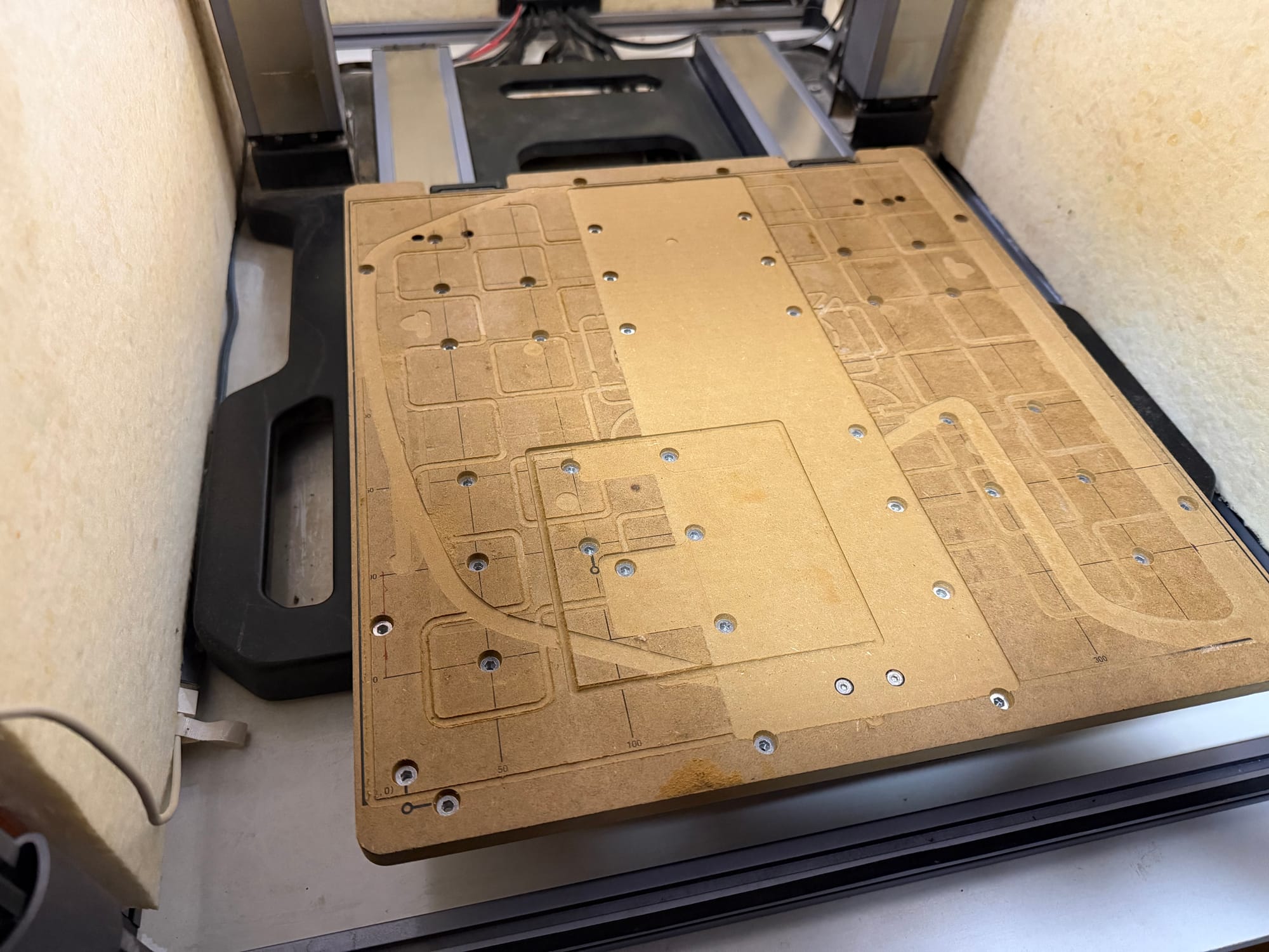
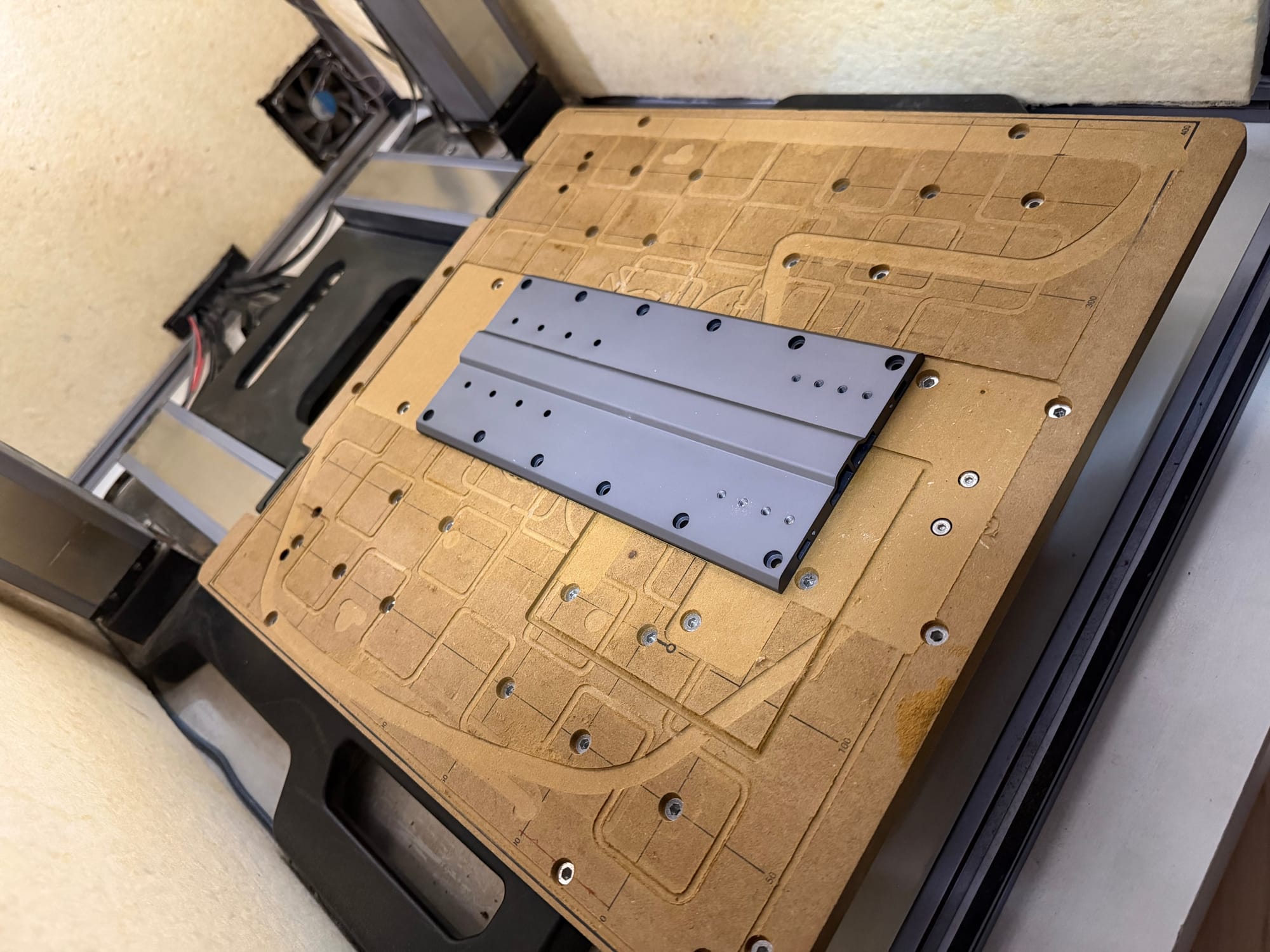
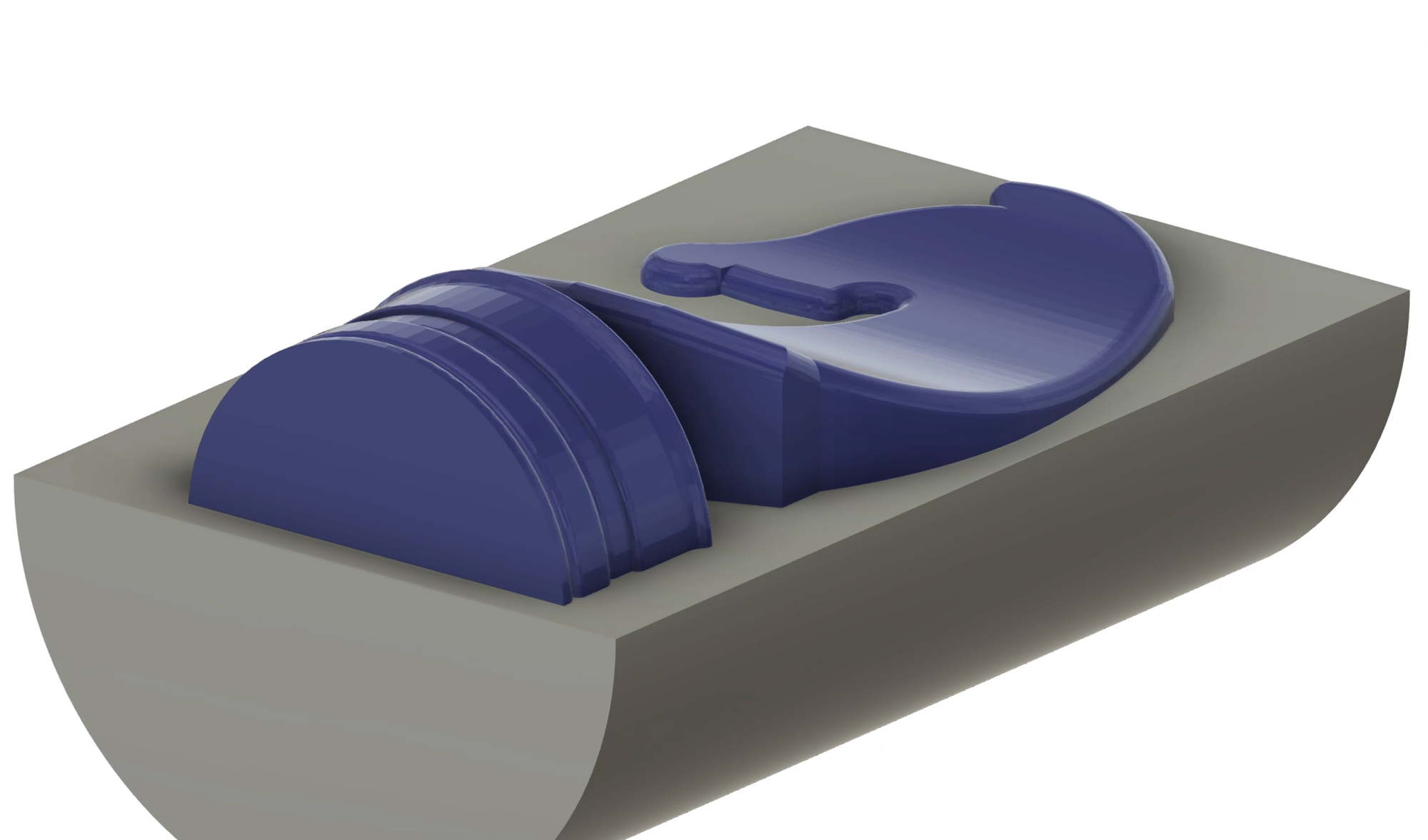
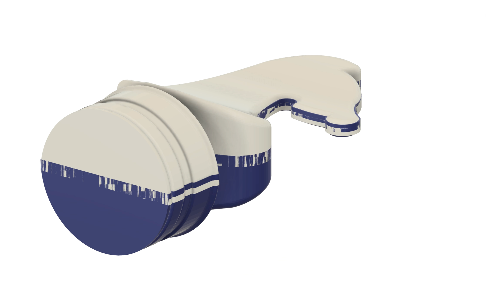
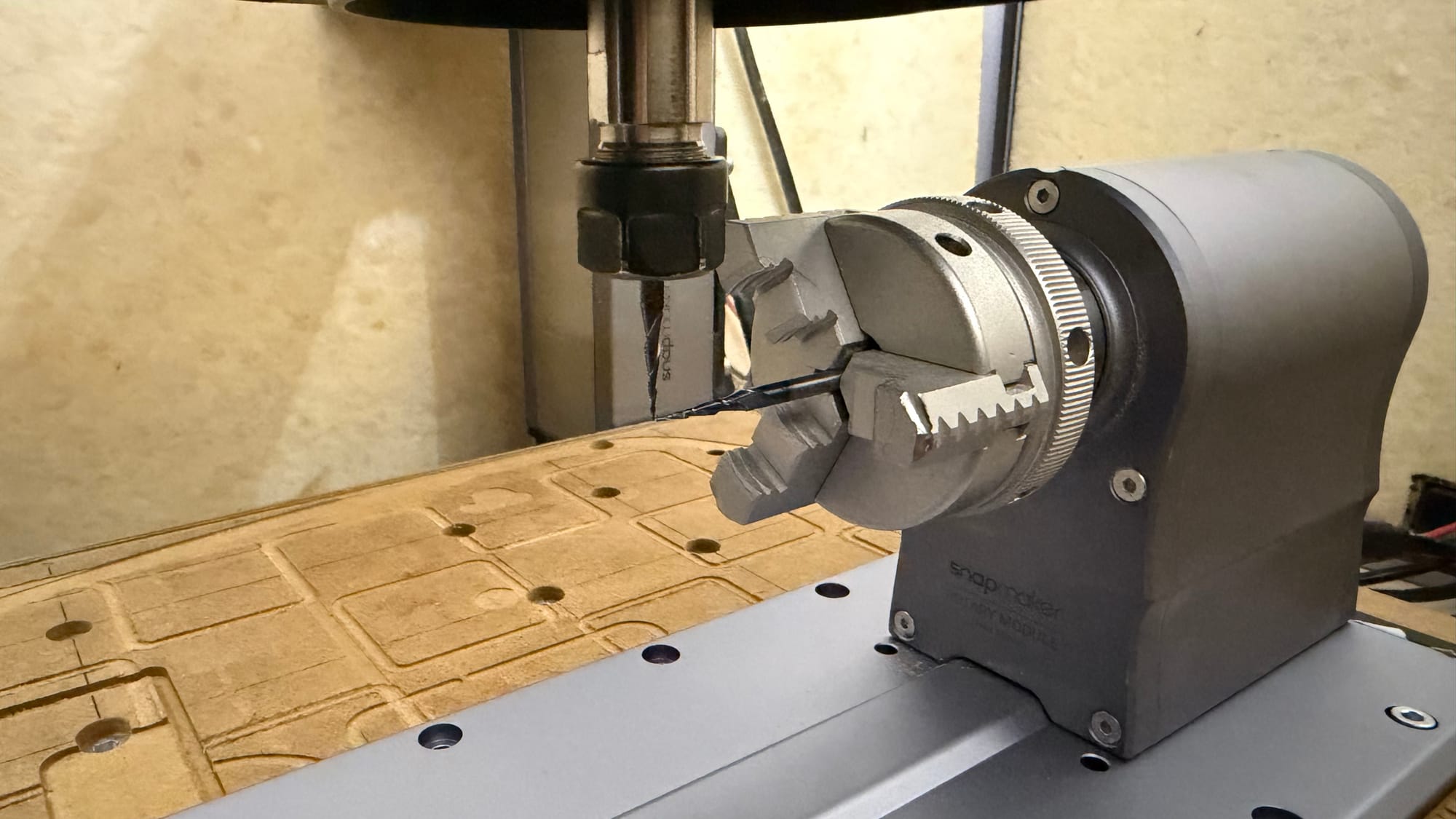
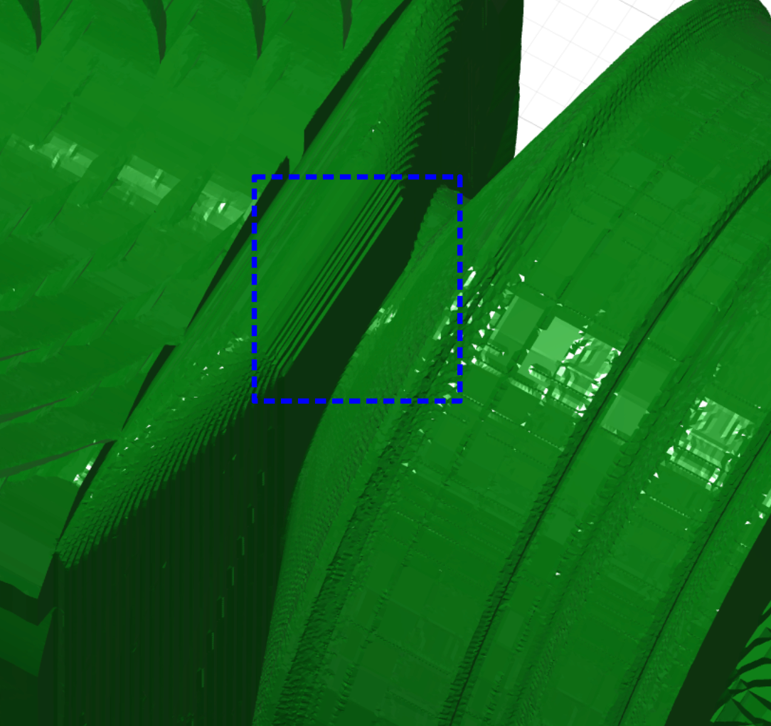
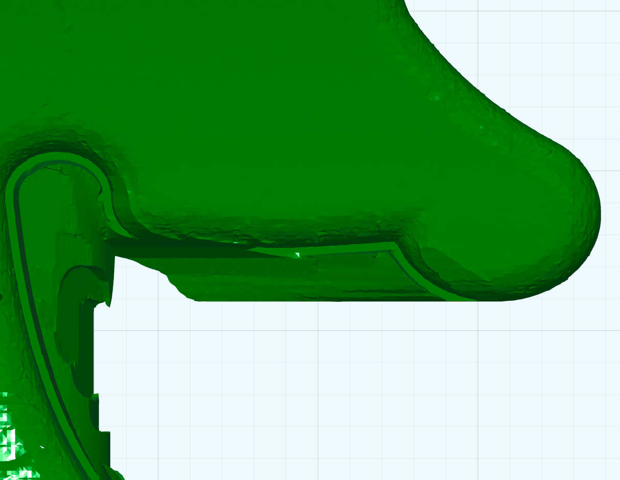
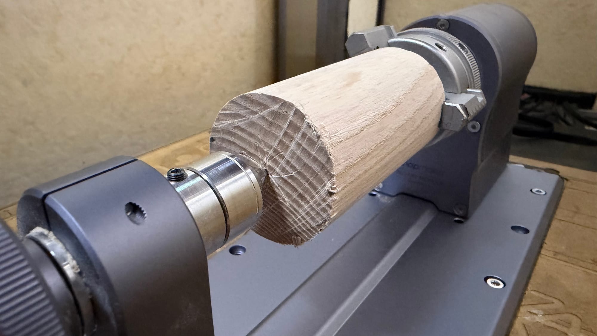
First, the rotation module must be fixed to the CNC Carving and Cutting Platform (hereafter referred to as the sacrificial plate) in such a way that the rotation axis is exactly parallel to the y-axis of the milling machine. The following 3 pictures show what happens if the axis deviates only slightly from this. As an example, the horse is milled in two steps. First, the upper half is machined, then the blank is rotated 180 degrees and finally the other half is machined. Since the rotation axis was slightly inclined to the y-axis, the two halves of the horse are now also slightly inclined to each other, which can be seen at the edge.

Since the sacrificial plate itself is not perfectly parallel to the axes and is not the same height everywhere, I recommend milling a recess for the rotation module as shown in the pictures, which corresponds as closely as possible to the width of the module. This allows you to align the edge of the rotation module parallel to the edge of the recess before screwing it in place, ensuring that the rotation axis is exactly parallel to the y-axis.
2.2: Precise and reproducible zero points
If you have already worked with the milling machine, you know that you have to set the zero point, the reference point for the coordinate system, in the software and later also zero the milling machine as precisely as possible to this point, i.e. set the work coordinates accordingly. For a planar milling project, you do not have to work with complete precision here, and it usually does not matter if your starting material is not perfectly flat. A deviation in the zero point simply shifts your object back and forth within the starting material.
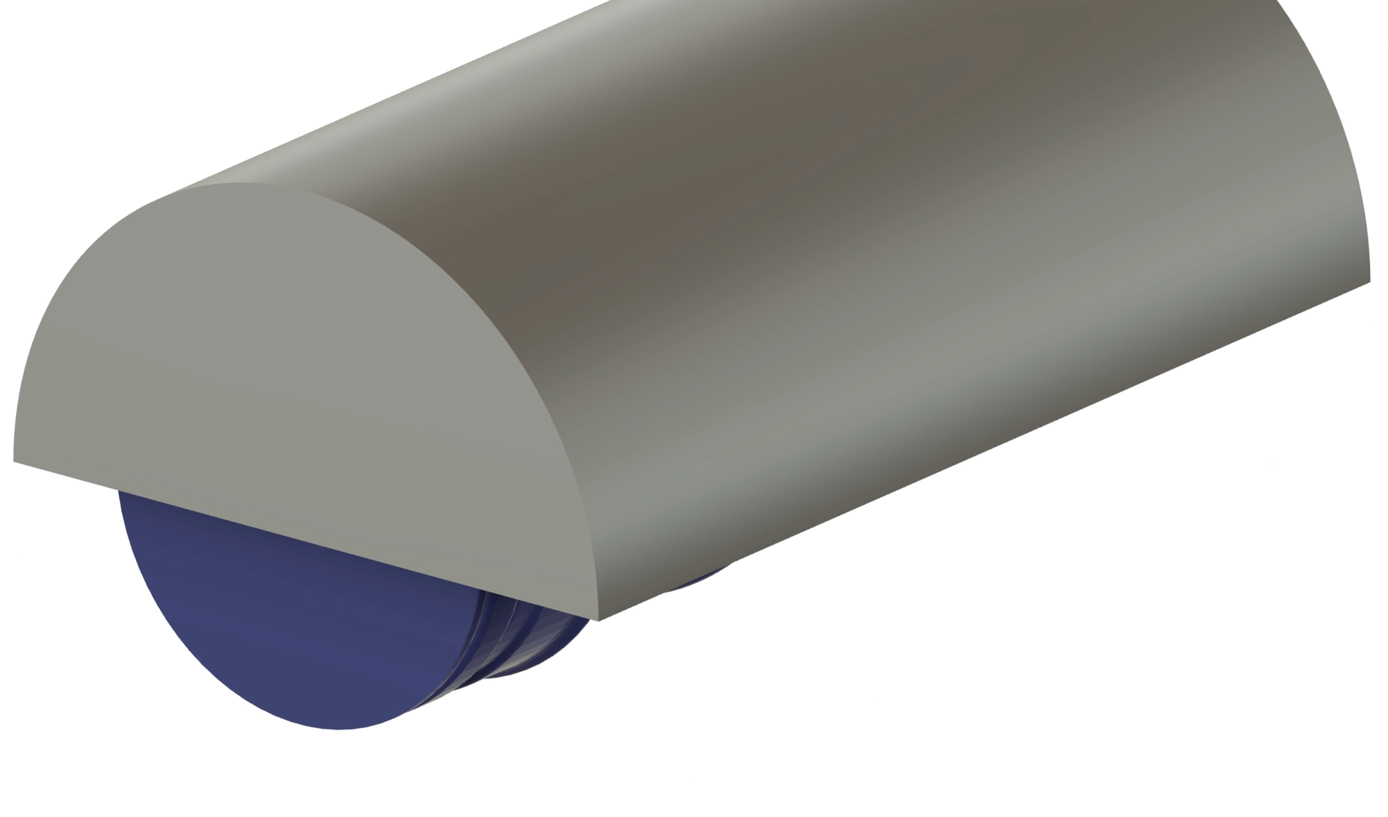
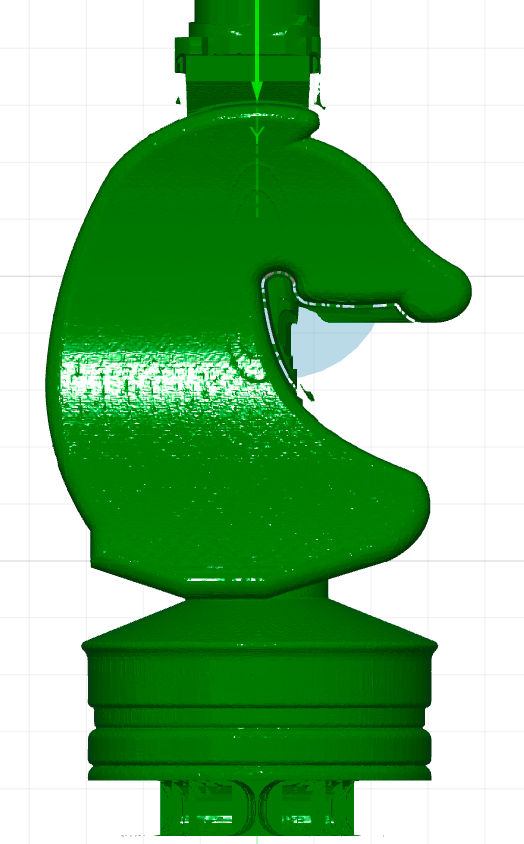
In a 3D milling process with the rotation module, a slight deviation between the zero point in the software and the point at which you actually zero can cause your finished object to be stretched or compressed. In the example below, you can see what would happen if your zero point had a z-coordinate that was too low. The two halves are now pushed into each other and the figure appears compressed.
My solution to this problem is to determine the coordinates of the rotation axis relative to a point on the body of the rotation module once. Once this offset is known, I can always zero my milling head at this point in the future, then manually move it by this offset and zero it again. This allows me to always set the zero point perfectly on the rotation axis.
Determining the displacement:
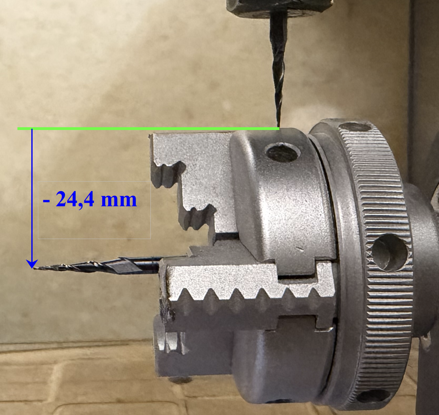
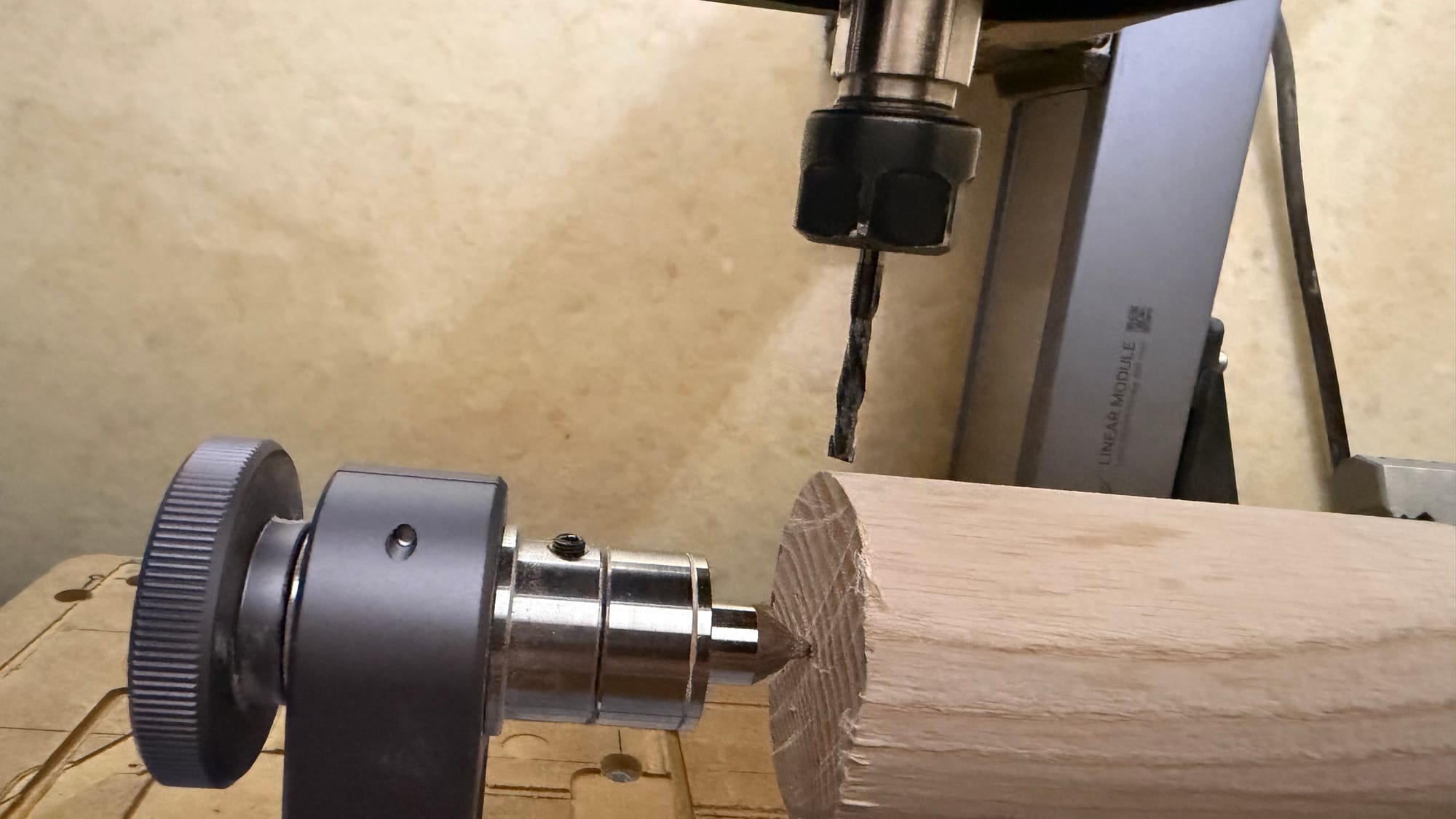
As can be seen in the pictures, I clamp a V-cutter with a narrow tip into the rotation module and the milling cutter and move the CNC manually by eye as accurately as possible so that the x and z coordinates of the two tips match and zero the milling head. I note down the absolute x-coordinate as the x-coordinate of the rotation axis. I then move the milling cutter to a fixed point on the module, as shown below, and note down the z-coordinate of the work coordinates. In my case, this was 24.4 mm, as can be seen in the pictures.
In practice, I can now always set the xyz coordinates one after the other as follows:
(1) The milling cutter is moved to the noted x-coordinate and x is reset to zero.
(2) The milling cutter is moved to the fixed point and z is reset to zero.
(3) The milling cutter is moved far to the side and lowered by the noted z displacement (24.4 mm in my case) and z is reset to zero again.
(4) The milling cutter is moved to the desired y coordinate and y is reset to zero. Personally, I always place my coordinate origin at the end of the stock material, but this is not mandatory.
(2) (3) (4)
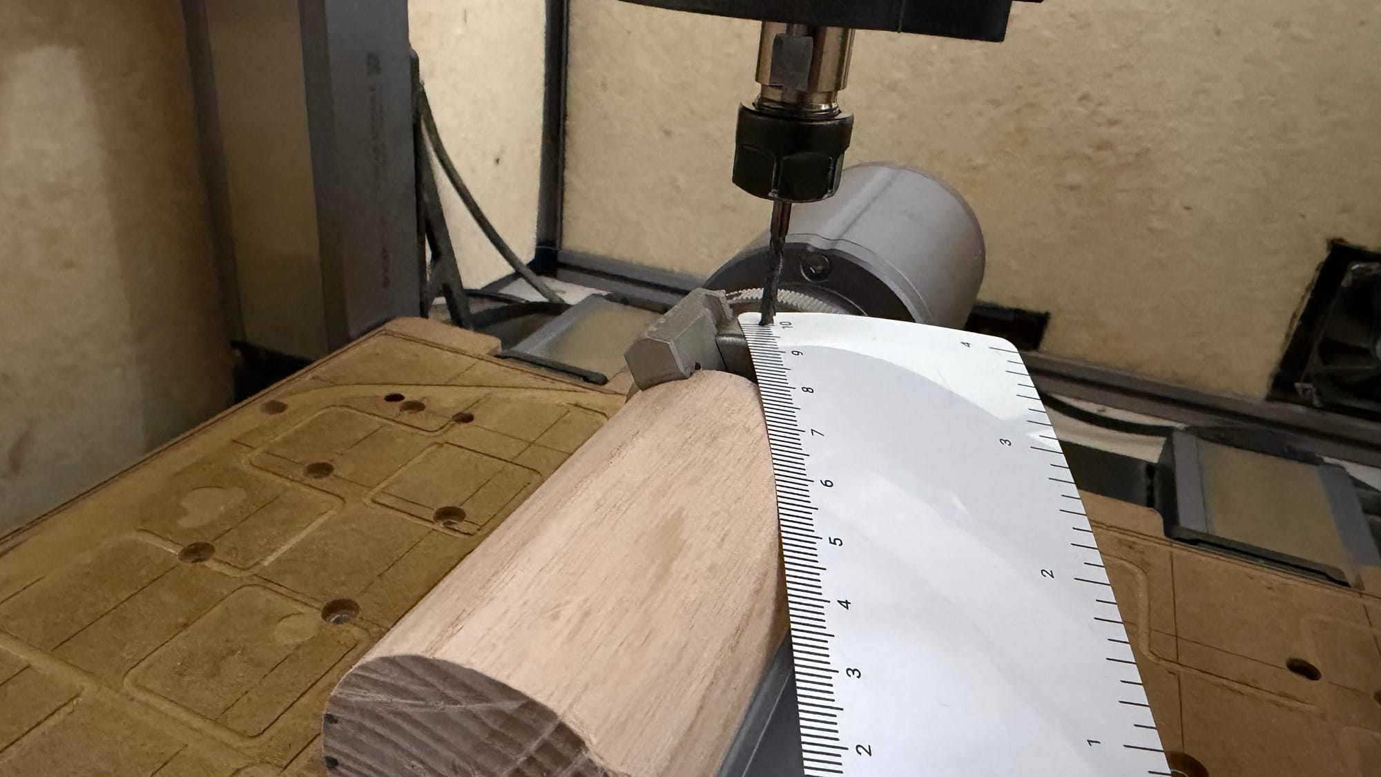
Some of you may be wondering why I don't just set the origin at the surface of the stock material. The problem is that this only works if you clamp your stock material perfectly straight and the blank is also perfectly flat and evenly machined. For example, I used wooden cylinders. If these are not perfectly round, it won't work.
3. Path generation with Fusion 360
In the following, I will go through the essential steps for creating the milling paths with Fusion 360 using the example of the horse. For this purpose, I am using a free 3D model instead of the paid one from my actual set so that you can test it out for free.
3.1: Preparing Fusion 360
First, you should install Snapmaker's PostProcessor for Fusion 360 and the tool library. Please follow the tutorial below:
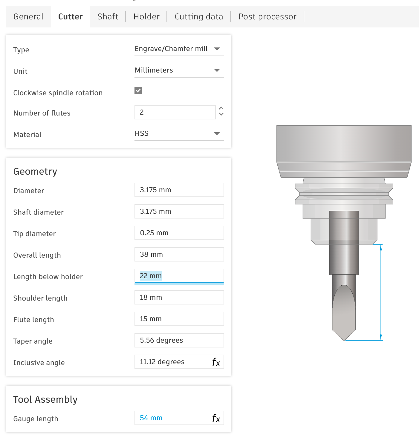
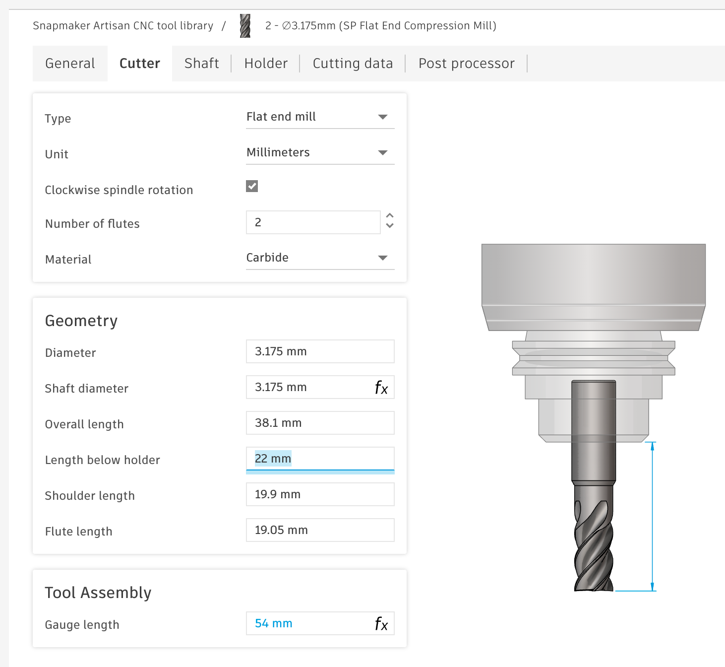
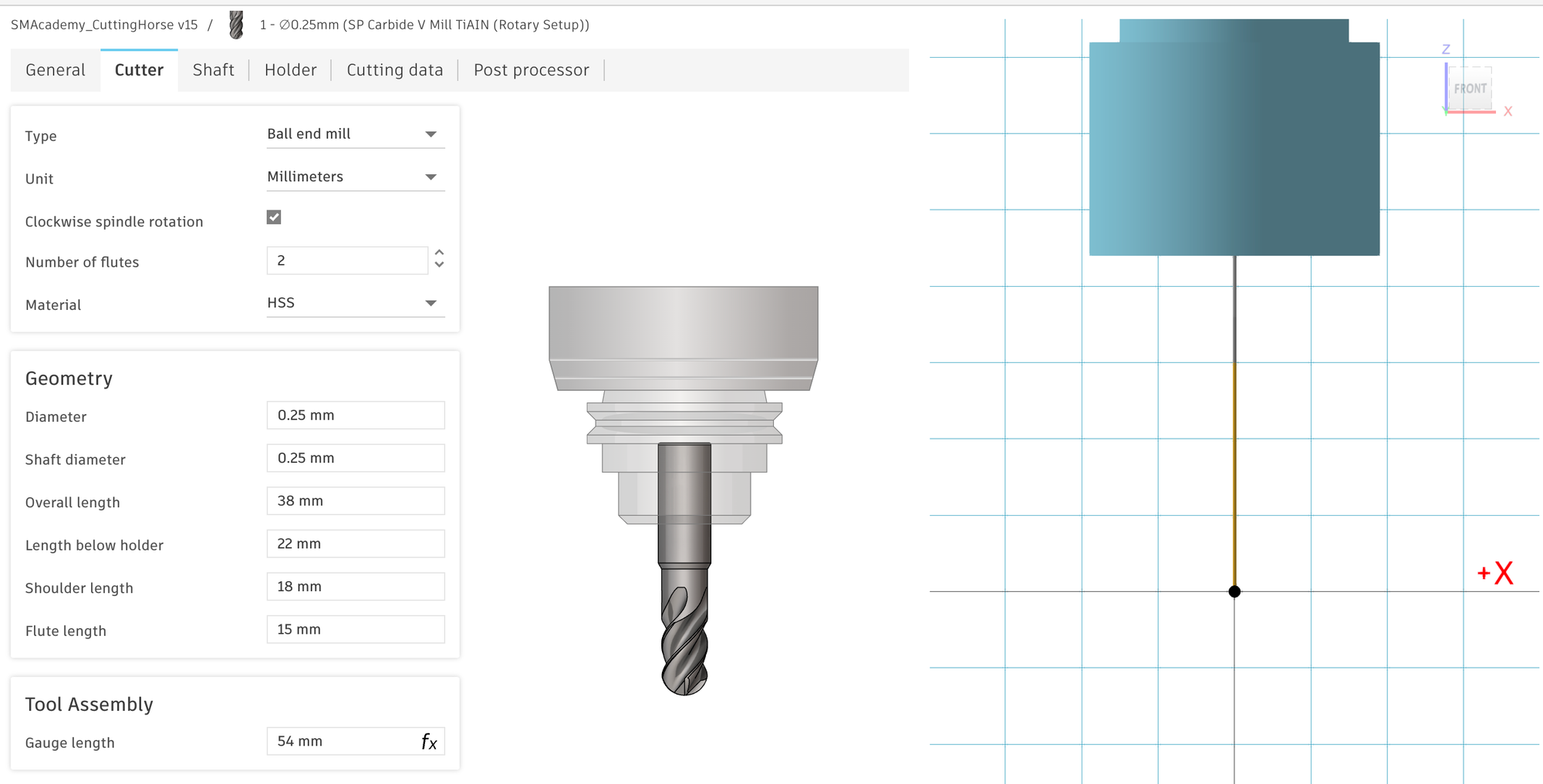
Selection of tools: For the figures, I used a 3,175 mm flat end compression bit from SP-Tools with 2 flutes for roughing and a V-mill with 2 flutes and a 0.25 mm tip from SP-Tools for finishing. However, you should also have no problems with the flat end mill and the V-mill that came with the Artisan.
In any case, you will need to check the cutter data for the tools in the tool library, as it may not be completely correct or may be incomplete. The following images show my settings for the SP tools. In particular, you should check the ‘Length Below Holder’ setting and add the correct holder for the first time. For the Artisan, this is a holder with a gauge length of 32 mm. If these settings are incorrect, it is possible that milling paths will be calculated in which the cutter holder will be rammed into your workpiece.
In the next few sections, I will walk you through path generation in Fusion 360. You can also download my finished project file here and insert it into Fusion: https://a360.co/4shdOrk
3.2: Inserting the 3D model and necessary placeholders
In this tutorial, I am using the horse from the following free model set: https://cults3d.com/en/3d-model/game/chess-theprinter_i
The horse is the most complicated piece in the set, which is why I chose it for the tutorial. In general, it is easier if larger parts of the figure are rotationally symmetrical. However, the figures are all milled in two steps – first, rough machining with the larger flat end mill, followed by longer, finer machining with the V-mill. To better control when which tool will be used to machine which areas, use placeholders, among other things, which are initially left out during milling:
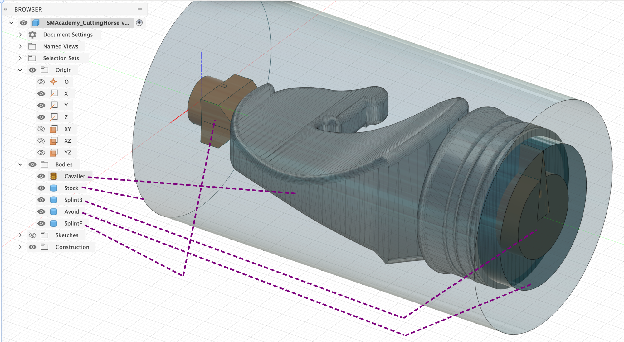
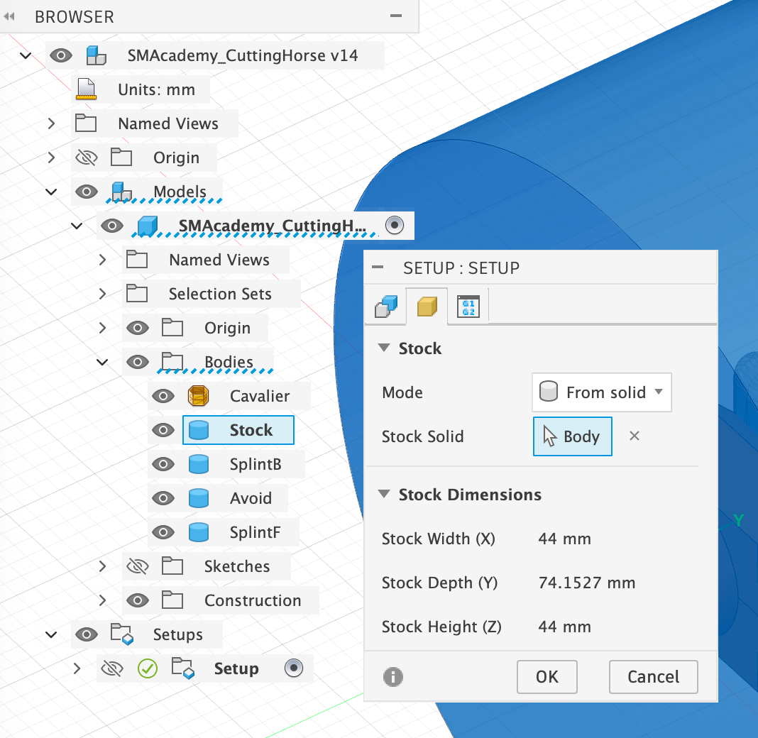
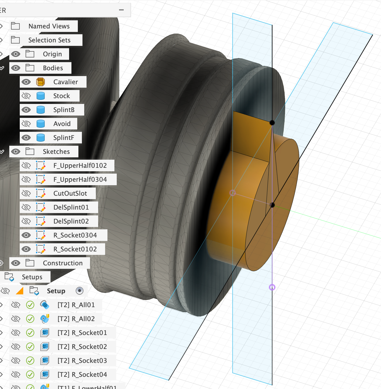
- Stock: This cylinder represents the piece of ash wood round bar with a diameter of 44 mm from which the figure is to be milled.
- SplintB & SplintF: These are two placeholders that should be left out by the milling machine almost until the end so that the figure does not slip out of the rotation module's holder during processing and does not start to vibrate too much.
You should always adapt the shape of SplintF to the ‘head shape’ of your figure so that you have less reworking to do later.
SplintB has a tip so that you can always tell which way is up and which way is down, especially after the first rough machining. This is because the clamps of the rotation module can come loose slightly during machining, causing the entire blank to twist slightly. This is not a big deal during rough machining, as there is still enough material left over. You can then use the tip as a guide to fix the blank correctly again and continue with the fine machining.
- Avoid: This cylinder is omitted, especially during fine machining with the V-mill, as the bottom of the figure can be machined better with the flat end mill anyway and any unevenness can be easily sanded away afterwards.
For the individual milling processes, we will also use sketches to limit the space in which the milling cutter is allowed to move. However, I will discuss this in more detail at the appropriate point.
3.3: Manufacture – Creating the milling paths
It would go beyond the scope of a text-based tutorial to go into every single setting in the various Fusion 360 menus and explain what each one means. Instead, I will only explain those that are particularly relevant to this project and otherwise simply provide my settings in the form of screenshots. If you have never worked with the Manufacture module of Fusion 360 before, I recommend that you watch the following video to understand the basics before continuing:
3.3.1: Setup settings
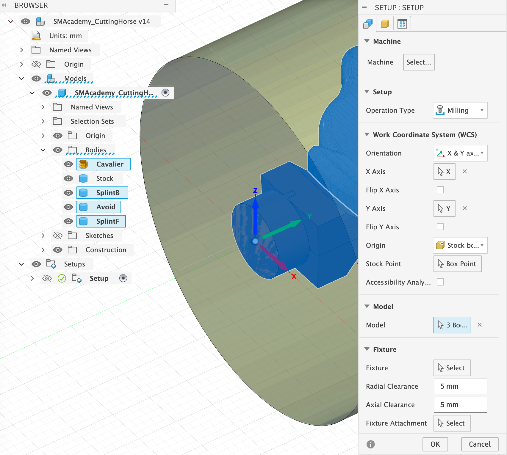
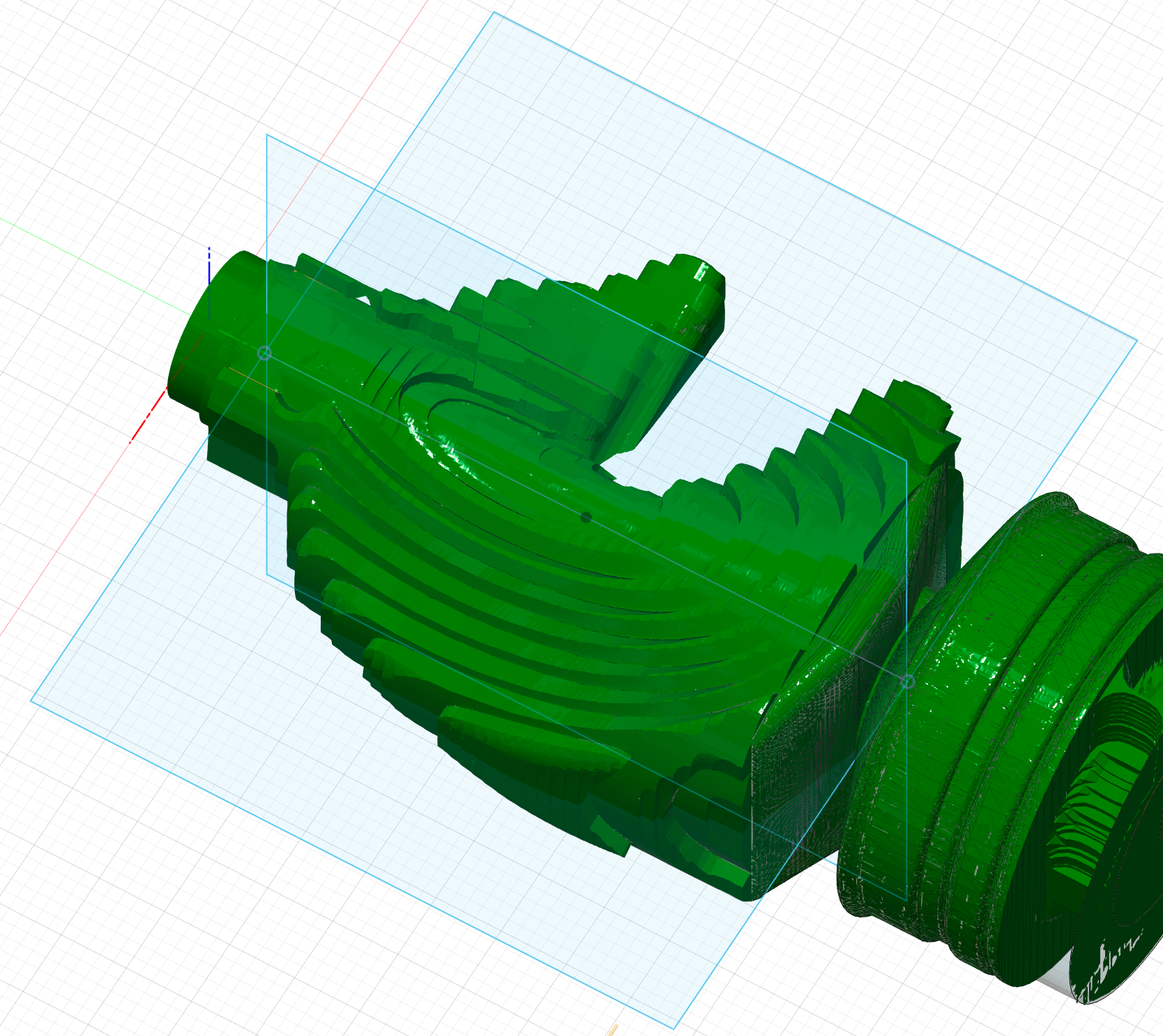
During setup, you essentially only need to select the correct stock body and set the coordinate system correctly so that the rotation module can work correctly later on. As already mentioned, I always set my coordinate origin to the rotation axis at the very end of my stick material. To do this, I simply aligned the material cylinder in Fusion 360 along the y-axis of the Fusion 360 coordinate system and was therefore able to simply adopt the standard coordinate system for the setup, as shown in the image:
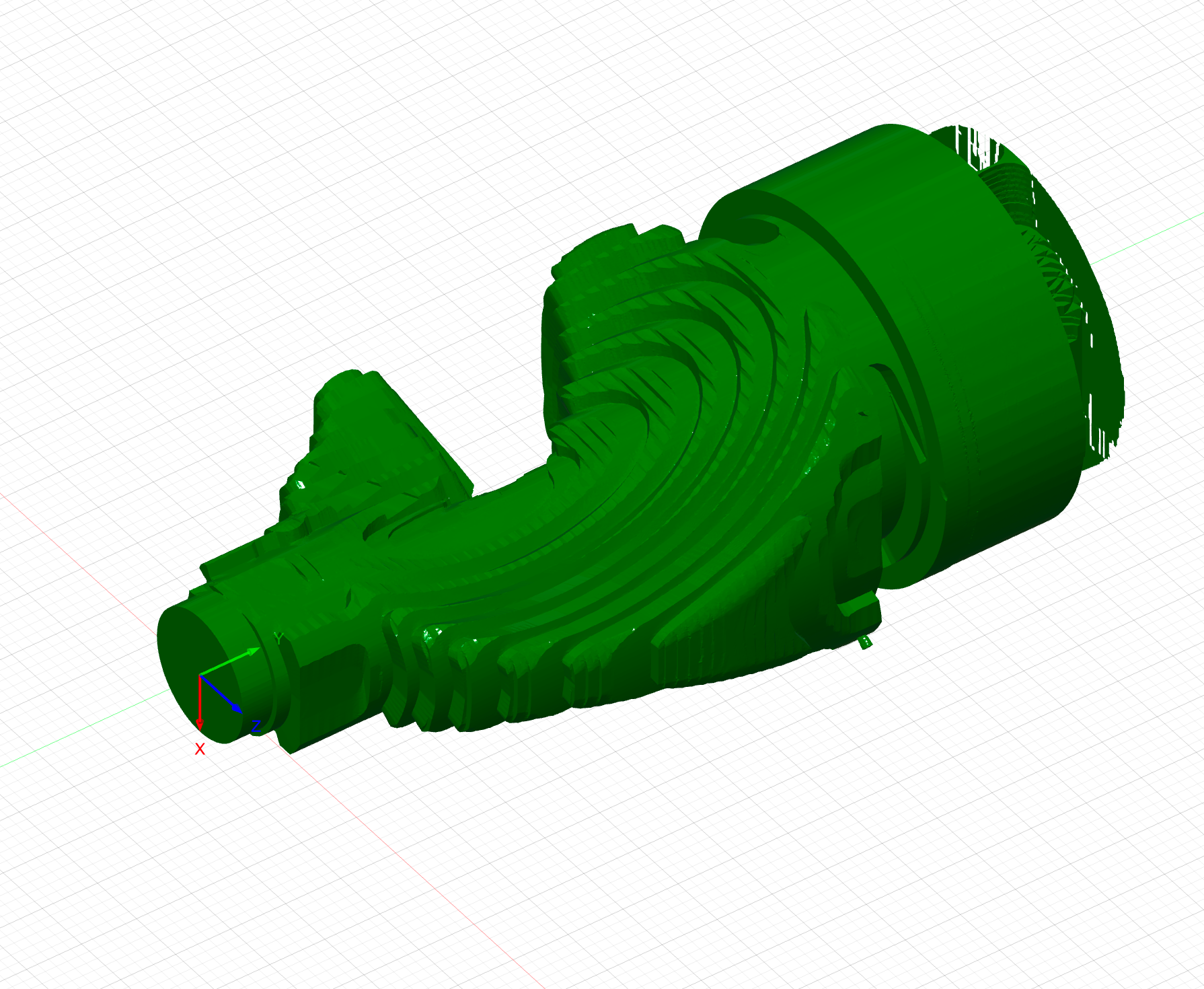
3.3.2: Rough machining with the flat-end mill
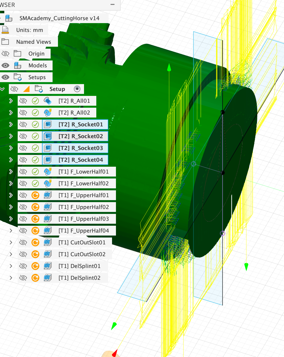
The aim of machining with the flat-end mill is to mill out the figure to 1 mm of residual material and to smooth the underside of the base, as the flat-end mill is better suited for this. This will be done in the steps shown, whereby the milling machine itself will later perform these steps as a single operation without further intervention:
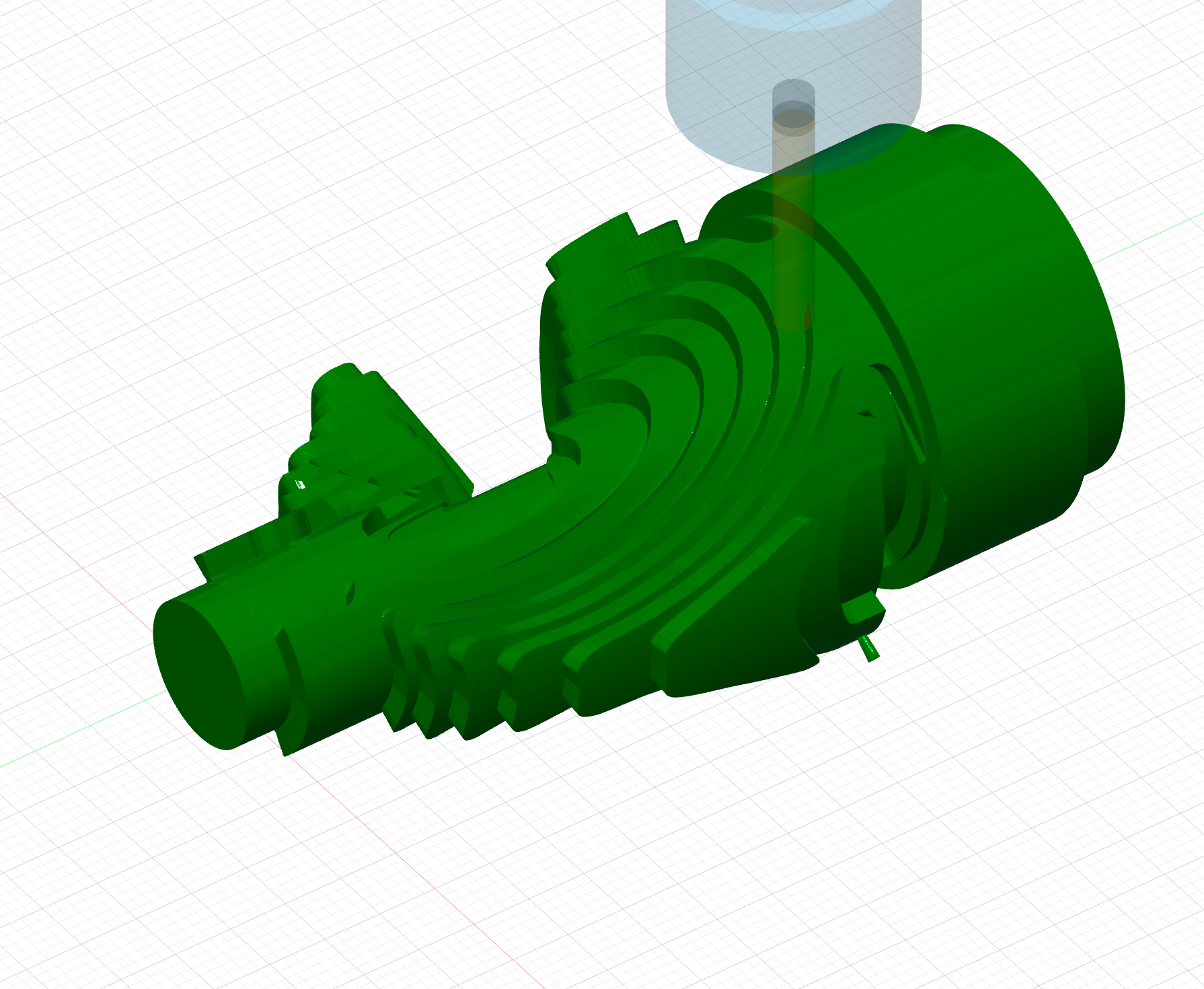

Using a combination of the two milling methods, Rotary Pocket and Rotary Parallel, we first machine the entire figure with the exception of the underside. These methods are only available if you activate the Machining Extension, which is usually subject to a fee. However, you can also replace all Rotary methods with several Adaptive Clearing operations – once from each side. I use this method when machining the base, among other things, and you can simply copy my approach from there if you do not have access to the Machining Extension.
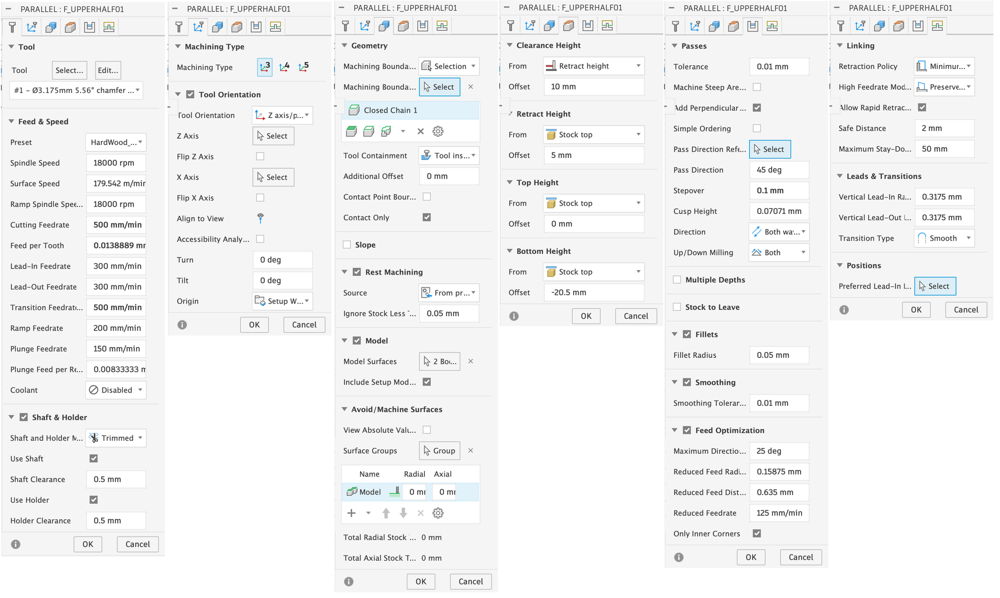
Below, I will show you the selected settings for the first milling operation with Rotary Pocket and explain a few selected settings:
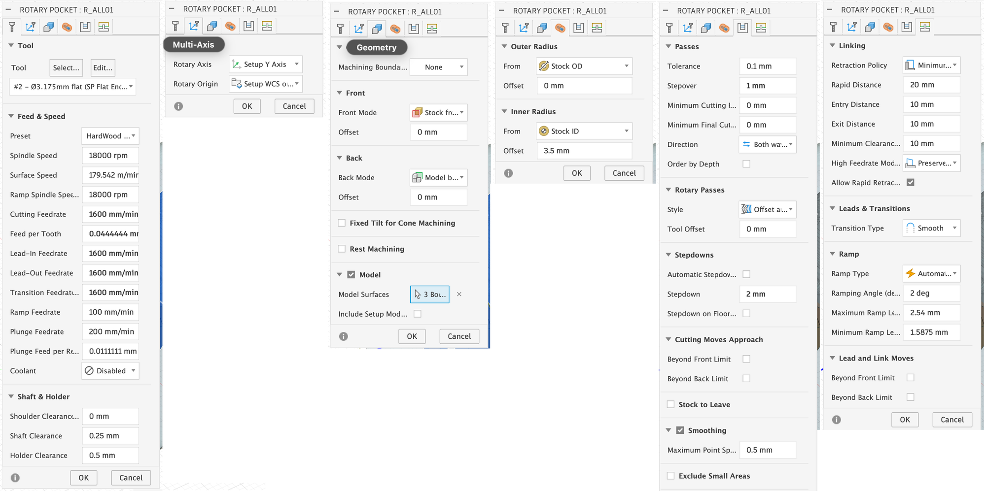
- Feed & Speed: The values here are relatively conservative, as time was not a major factor for me. The main problem with machining too quickly is that you can cause stronger vibrations in the material, which can cause the entire workpiece to come loose from the collets, meaning you can then discard it.
- Shaft & Holder: Here you specify the safety distance to be maintained from the rest of the material when milling and moving the milling head. It is important to note that Fusion 360 only attempts to adhere to these specifications, but does not always manage to do so reliably. You must therefore check later in the simulation whether any collisions have occurred.
- Rotary Axis: In my example, the y-axis of the coordinate system must be selected here. This will then serve as the axis of rotation for the Rotary module.
- Model Surfaces: We select all objects except the stock body itself. These are the objects that are to be milled. Note that it says ‘3 Body’ here, because the horse itself is a mesh and was therefore selected, but is not counted when counting the selected ‘bodies’.
- Outer & Inner Radius: Determines the distance from the axis of rotation at which the tip of the milling cutter is allowed to move. It is important that you select an inner radius that is large enough to prevent the milling cutter from penetrating the material so deeply that your holder collides with the material. Compare the difference between these two values with your value for ‘Length below Holder’ for your tool.
- Stepover & Stepdown: These two values determine how deep the cutter may penetrate the remaining material for each milling operation and how large the lateral distance between the individual milling paths will be. You will need to play around with these values a little, depending on the shape, to achieve a good result. I would not recommend choosing paths that are too deep, as this can cause various problems. If the cut is too deep during CNC milling, the load on the tool increases significantly, which can easily lead to tool breakage. Fragments can damage the workpiece and leave scratches or indentations. In addition, the surface quality deteriorates because excessive feed rates create visible tool marks and steps that are difficult to remove later. Recommended parameters for 200W CNC can be found here for reference. https://wiki.snapmaker.com/en/general/recommended_parameters_for_200w_cnc_module
- Stock to Leave: This is not necessary here, as it should only mill to a depth of exactly 2 mm anyway, leaving anything less than 2 mm of residual material.
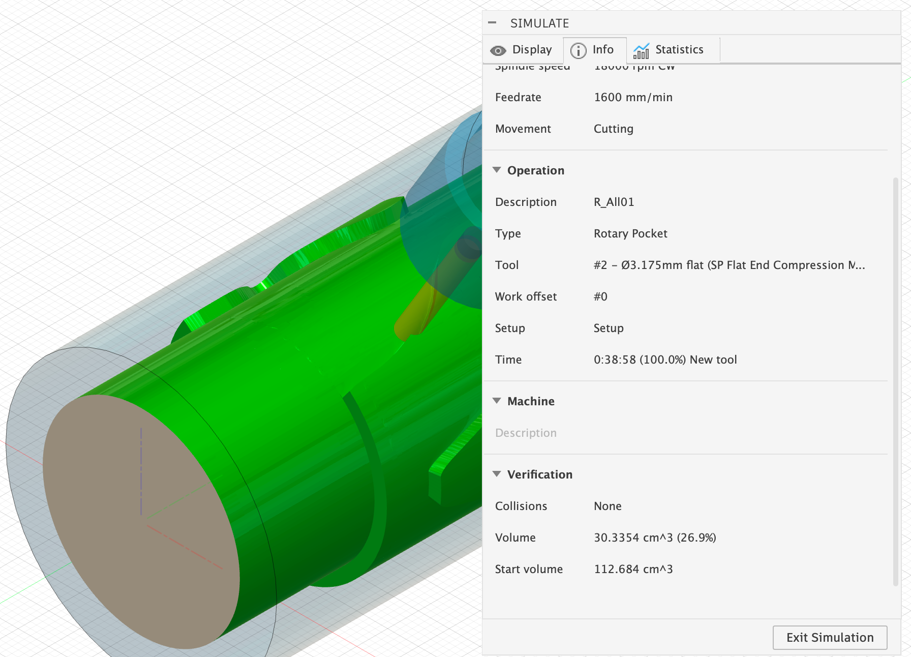
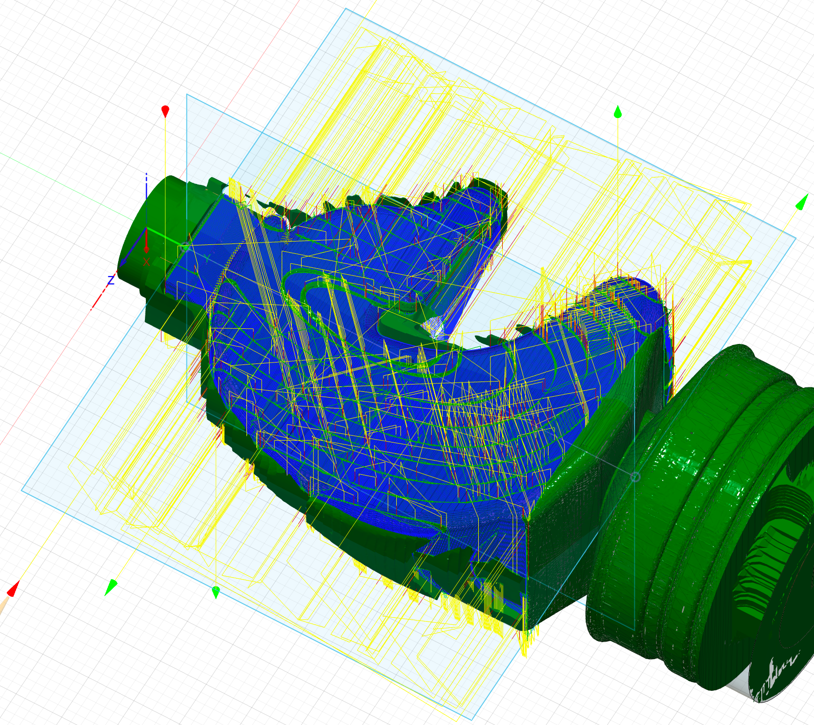
Once your milling process has been calculated, be sure to start the simulation under Actions > Simulate. There, check under Info > Verification to see if there have been any collisions (see image on the right). If so, you may need to adjust your inner radius again.
The following rotary parallel method is used to machine the areas that have not yet been milled down to 1 mm of residual material. Otherwise, in my experience, the remaining machining with the V-mill takes too long.
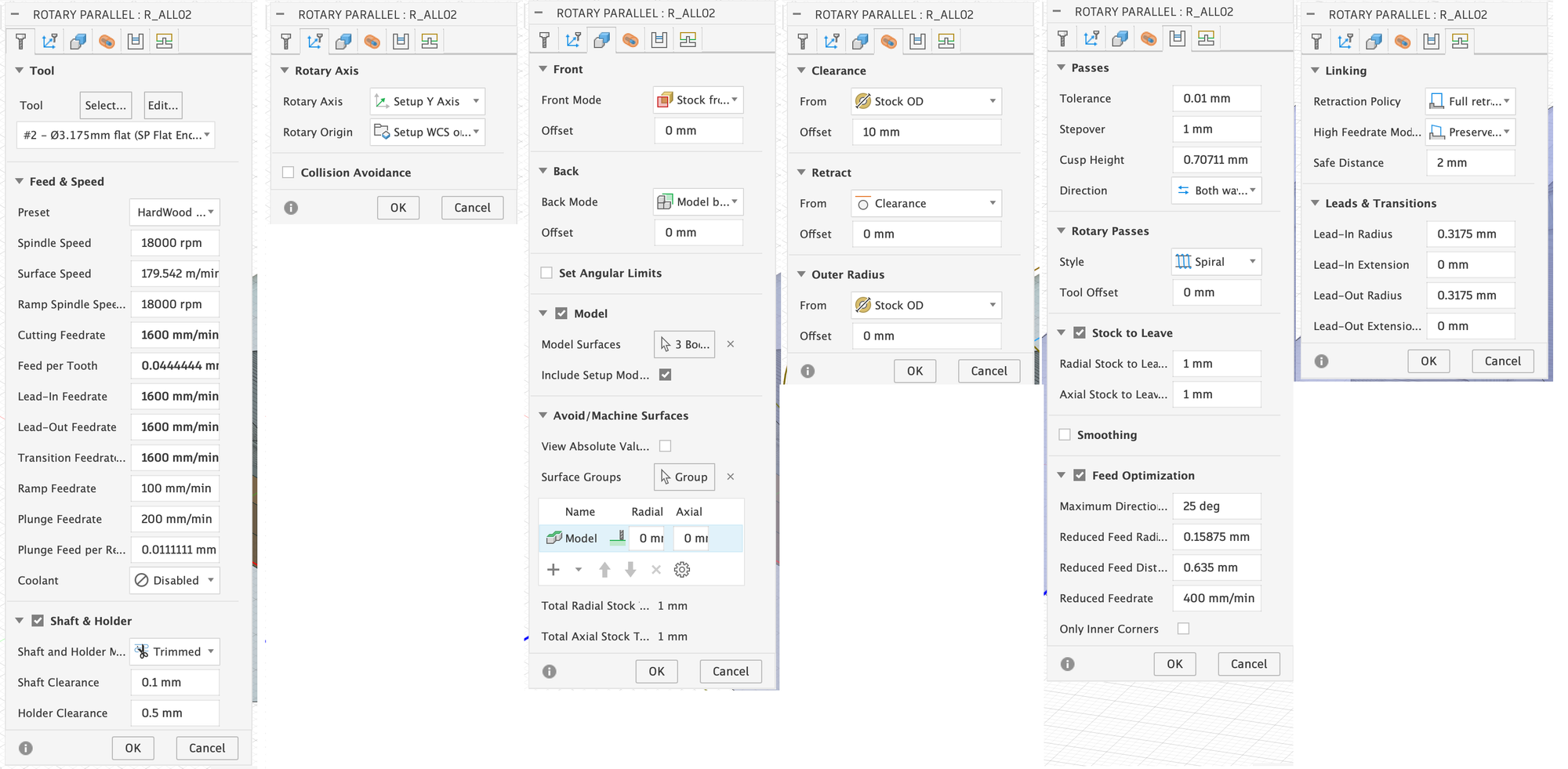
- Stock To Leave: With Rotary Parallel, the workpiece is continuously rotated and the milling head simply raises and lowers to maintain a fixed distance from the desired model, which is set here in Stock to Leave.
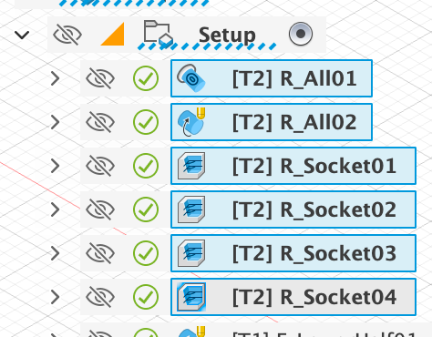
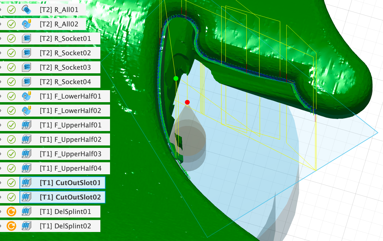
Finally, the underside of the base is to be machined using the flat end mill, whereby we will cut out the ‘SplintB’ as announced. To do this, we use the ‘Adaptive Clearing’ method once on each of the four sides:
Since in this case we want to mill down to the model, we have to limit the milling process with the help of the sketches shown ‘R_Socket…’, otherwise Fusion will try to completely machine the rest of the horse as well. Using the example of the first clearing process ‘R_Socket01’, I will show you below where you need to set this:
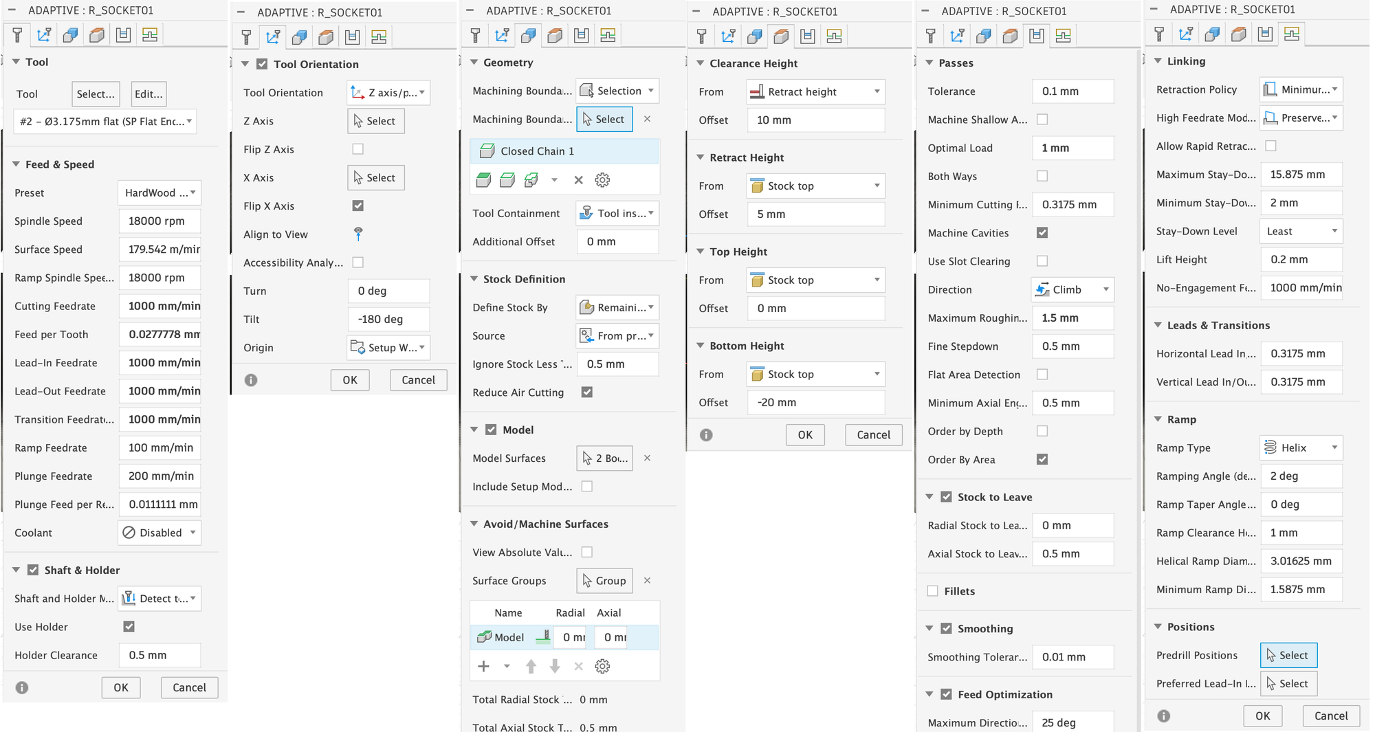
- Tool Orientation: Using the Tilt setting, you must rotate the displayed coordinate system in the direction from which you want to mill. In this case, I want to mill from the bottom first, which is why I rotated the coordinate system by 180 degrees. I had to activate ‘Flip X Axis’ here, because Fusion would otherwise also rotate the y-axis when rotating 180 degrees.
- Geometry: Here, the movement of the milling head must be restricted to the interior of the previously created sketch. To do this, select ‘Selection’ under Boundary, then click on the ‘Chain’ icon and select the rectangle from the sketch (see image below).
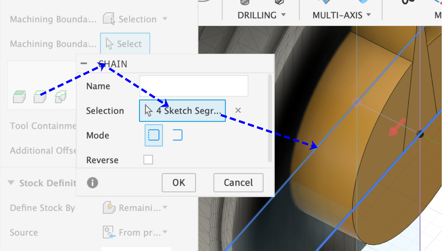
- Model Surfaces: Here, of course, the body ‘Avoid’ must now be omitted.
- Bottom Height: To avoid a collision between the holder and the base, I have set -20 mm relative to the top of the stock material. The cutter will therefore dive to a maximum depth of 20 mm.
- Optimal Load & Maximum Roughing Stepdown: These settings have essentially the same meaning here as they did previously for the rotary methods Stepover and Stepdown and must be set so that the vibration does not become too great during milling and the spindle speed of 18,000 can be maintained by the milling machine.
- Stock To Leave: The Radial Stock to Leave is set to 0, as the bottom is already to be finished.
Accordingly, the base is machined from above, left and right. The settings remain the same with the exception of the Tool Orientation and the selected Boundary.
3.3.3: Fine machining with the V-Mill
When fine machining, we want to carve out the figure as precisely as possible so that we have to do as little manual reworking as possible afterwards. With the figure used here, which has many smooth surfaces, this is of course not very efficient. However, the horse figure I actually made has finely chiselled fur and facial details that cannot simply be reworked with sandpaper.
Fine machining takes place in the following 3 steps:
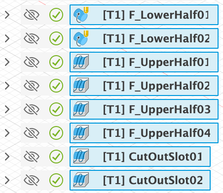

First, the base is carved out using rotary methods, and then the actual horse figure is milled using several parallel clearing processes. For the other figures, which are almost completely rotationally symmetrical, this second step is not even necessary. Finally, the rest is removed from under the horse's chin.
The base is to be machined using the rotary parallel method and the V-mill. However, Fusion does not allow V-mills with this method, which is why we have to resort to a little trick. To do this, I created a flat end mill with the V-mill data in the tool library, using the size of the V-mill tip as the diameter:
With this tool, we can then use the rotary parallel method. Please note that from this point on, the simulation will no longer correspond to reality, as in reality a 0.25 mm narrow flat end mill will not be used, but rather the V-mill. This will automatically cause problems if you try to machine a wall parallel to the tool in this way. The wall marked in the image on the right, for example, will receive a chamfer from the V-mill.
But if such problems can arise, why should the Rotary Parallel method be used at all? Of course, the base can also be finalized with, for example, an adaptive clearing process from above, below, left and right. The problem, however, is that this can lead to even more unpleasant problems if your axis of rotation was not perfectly aligned or you did not zero perfectly. In this case, you will always get a small visible edge or line where the areas processed by the four operations meet. Sanding this away by hand later can be very difficult.
Below, I will show you the settings for the first Rotary Parallel milling operation, which uses the virtual flat end mill, so to speak:
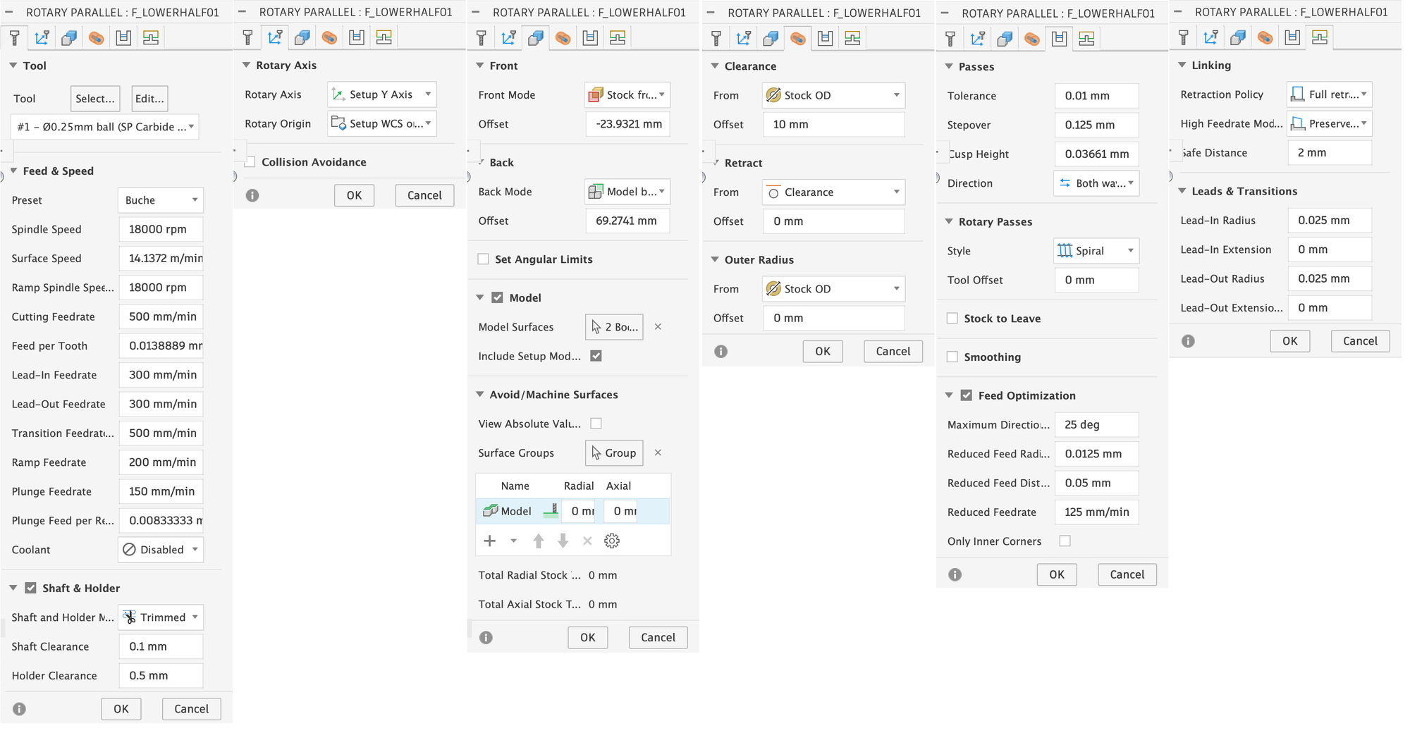
- Front & Back Offset: Here you can specify the area to be milled. We limit this to the base of the figure.
- Stepover: Here we use half the diameter of the tip of our tool to ensure that the surface is as smooth as possible.
We then repeat this process almost identically. We simply change the style to ‘Line’ under Rotary Passes and increase the cutting feed rate from 500 mm/min to 2000 mm/min. Without this, a noticeable and faintly visible pattern from the spiral movement of the previous milling process would remain, and some wood fibres would also remain, which would otherwise have to be laboriously removed later.
The upper half of the figure is finalised in a similar way to the first rough machining of the base, with a parallel clearing operation on each side, for which you will need to create two sketches again, as shown.
As with the base floor, the settings for the four individual processes differ only in terms of the orientation of the coordinate system and the boundary. Please note, however, that you should now use the actual V-mill for these processes and not the virtual flat end mill:
- Pass Direction: Specifies the angle at which the individual paths should be to the y-axis.
- Add Perpendicular Passes: If this box is checked, the entire milling process is repeated after completion, rotated by 90 degrees. This ensures that the milling paths do not remain as fine lines on the figure afterwards.
Finally, a small residue remains under the horse's chin. Theoretically, we could have avoided this by lowering the bottom height slightly in the previous steps. However, with the engraved horse model that I used in the original, this led to flaws in the mouth area, as Fusion 360 was unable to maintain the safety distances when attempting to merge further down. In this respect, I first had the model carefully machined from all sides and am only now removing the residue under the chin individually.
For this final step, we define the milling area with the aid of a sketch and then use the parallel clearing method from below and above with a bottom height that fits just right:
3.3.4: Removing the front support splint
In the case of the horse used here, we could stop now. The two splints ‘SplintF’ and ‘SplintB’ could simply be removed with a saw, as they are attached to smooth surfaces, and the areas could be sanded down by hand. However, the other figures have a ball or similar shape on their heads, which is difficult to achieve with a saw.
I therefore had the front splint ‘SplintF’ removed from each figure using the V-mill on the milling machine. The procedure here is the same as for removing the rest under the horse's chin. Depending on the shape of your splint and the head of your figure, milling from above and below may be sufficient, or it may be necessary to mill from the left and right as well.
It is important that you tighten the clamps on the rotation module again before performing this last step and retract the support that presses directly into the front splint to release the pressure on it.
3.3.5: Post-processing
If you have the post-processor as described in the instructions linked in 3.1, the milling operations can now be exported in a format that Luban can understand. Here, we can combine several milling operations into a single operation so that we do not have to constantly operate the milling machine later to start the next operation.
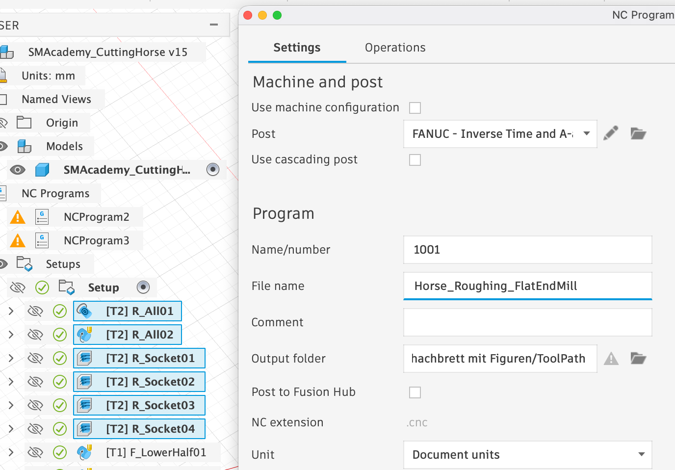
First, we select all milling operations that use the flat end mill and click on Post Process under Action. In the window that appears, we only need to select ‘Fanuc’ under Post, as this is the post-processor that supports the rotation module, and choose a meaningful ‘File Name’:
We do the same with the operations for fine finishing with the V-Mill and once with those for removing the front splint:
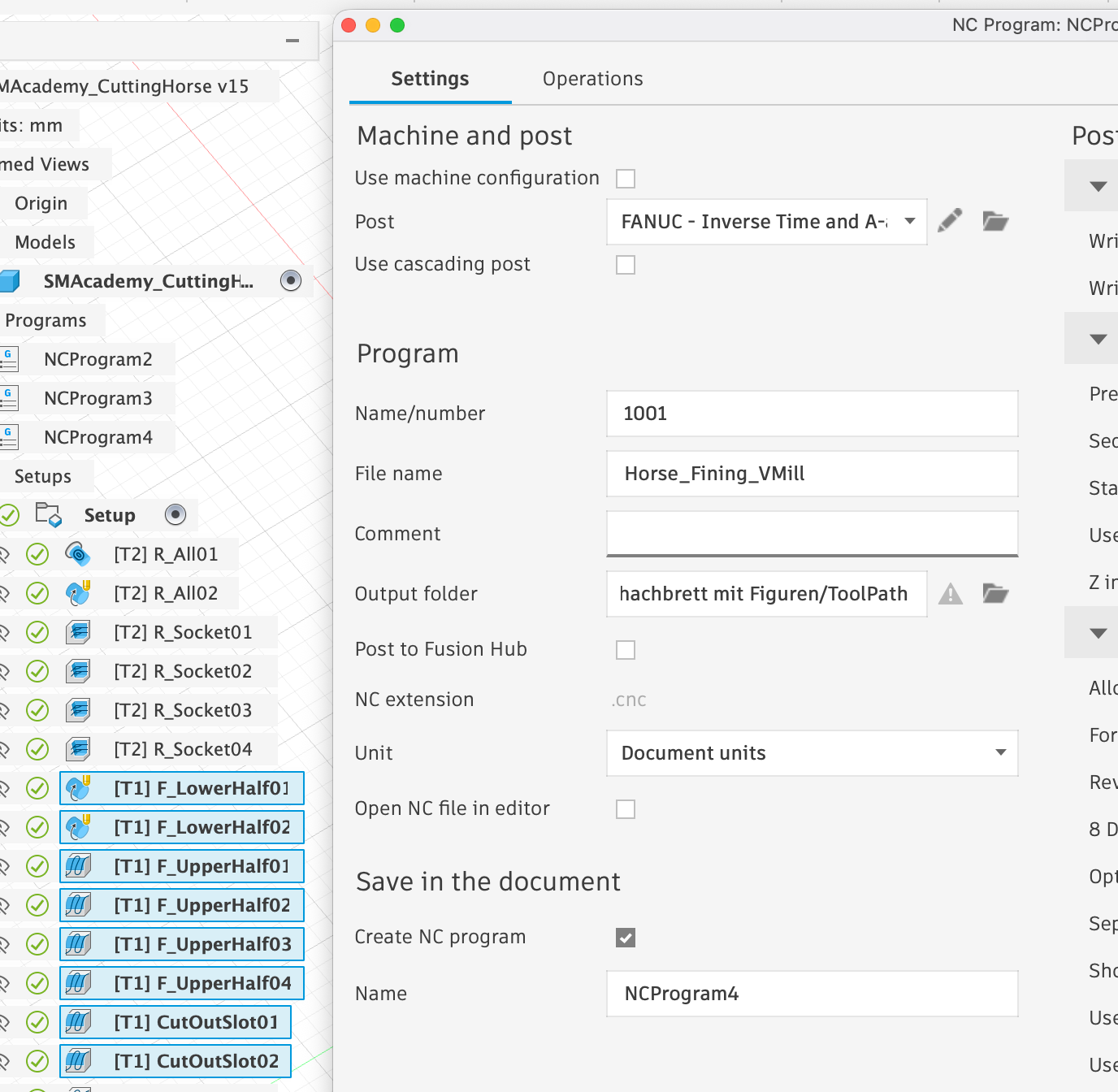
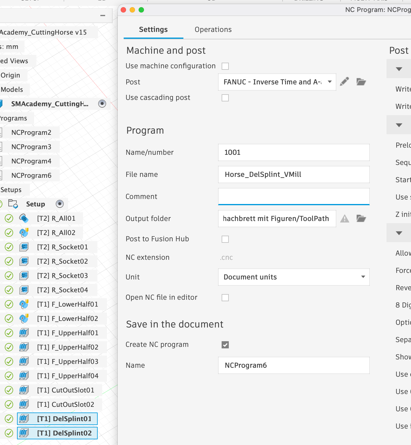
Ultimately, we end up with three files that we can send to the Artisan via Luban.
- Horse_Roughing_FlatEndMill.cnc
- Horse_Fining_VMill.cnc
- Horse_DelSplint_VMill.cnc
4. Practical implementation
4.1: Notes on milling
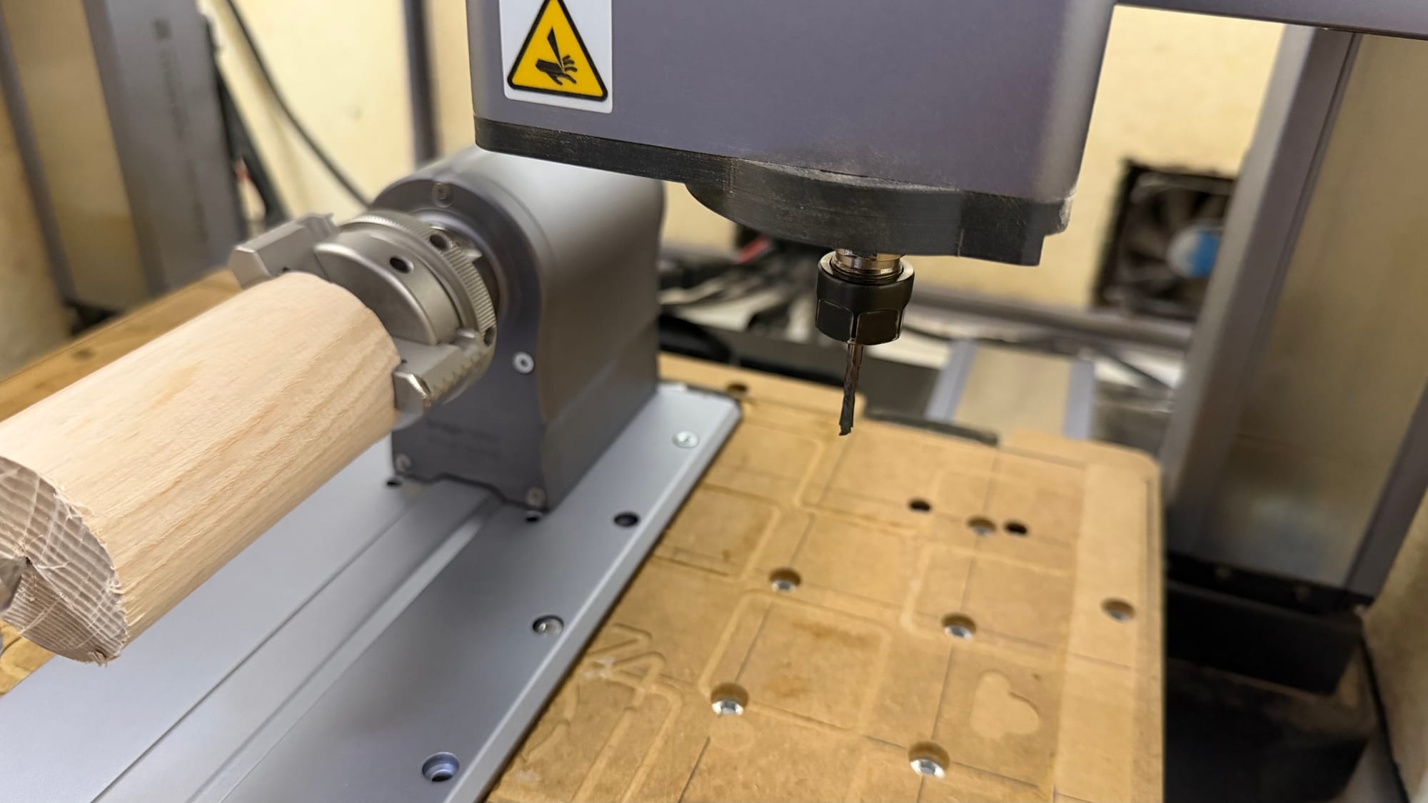
I used round ash wood rods with a diameter of 44 mm for the figures. It is important that you add about 2 cm to the length of the cylinder used as stock in Fusion before cutting the round rod to size for use. Otherwise, the milling cutter may collide with the collets of the rotation module during milling. In addition, you should mark the centre point of the cut surfaces of your round rod in advance so that you can position the additional support as centrally as possible when clamping the material.
After the initial rough machining using the flat end mill and ‘Horse_Roughing_FlatEndMill.cnc’, the tool must be changed to the V mill and the zero point must be reset according to the method explained in 2.2. Then ‘Horse_Fining_VMill.cnc’ can be executed. If this is successful, the support can be retracted and the splint removed with ‘Horse_DelSplint_VMill.cnc’.
You can watch the entire process in fast motion in the following videos, using the horse and queen from my set as examples. Please note that each figure took around 4-7 hours to complete in reality:
- Horse
- Queen
At this point, we would like to point out a bug. If you have exported several rotational milling processes together in Fusion, the rotation module may get stuck in an endless rotation loop after the process is complete. Although the cutter is moved upwards to a safe distance, the module simply continues to rotate endlessly instead of declaring the process complete. In this case, you must restart the machine and reset everything before continuing. The tip of the rear split pin (‘SplintB’) will help you to determine the correct alignment of the workpiece again.
4.2 Finishing the figure
There are countless ways to finish the figures. I decided to simply apply a thin coat of clear varnish to the white figures to make them shine and to colour the black figures beforehand with a dark stain that does not cover the grain of the wood.
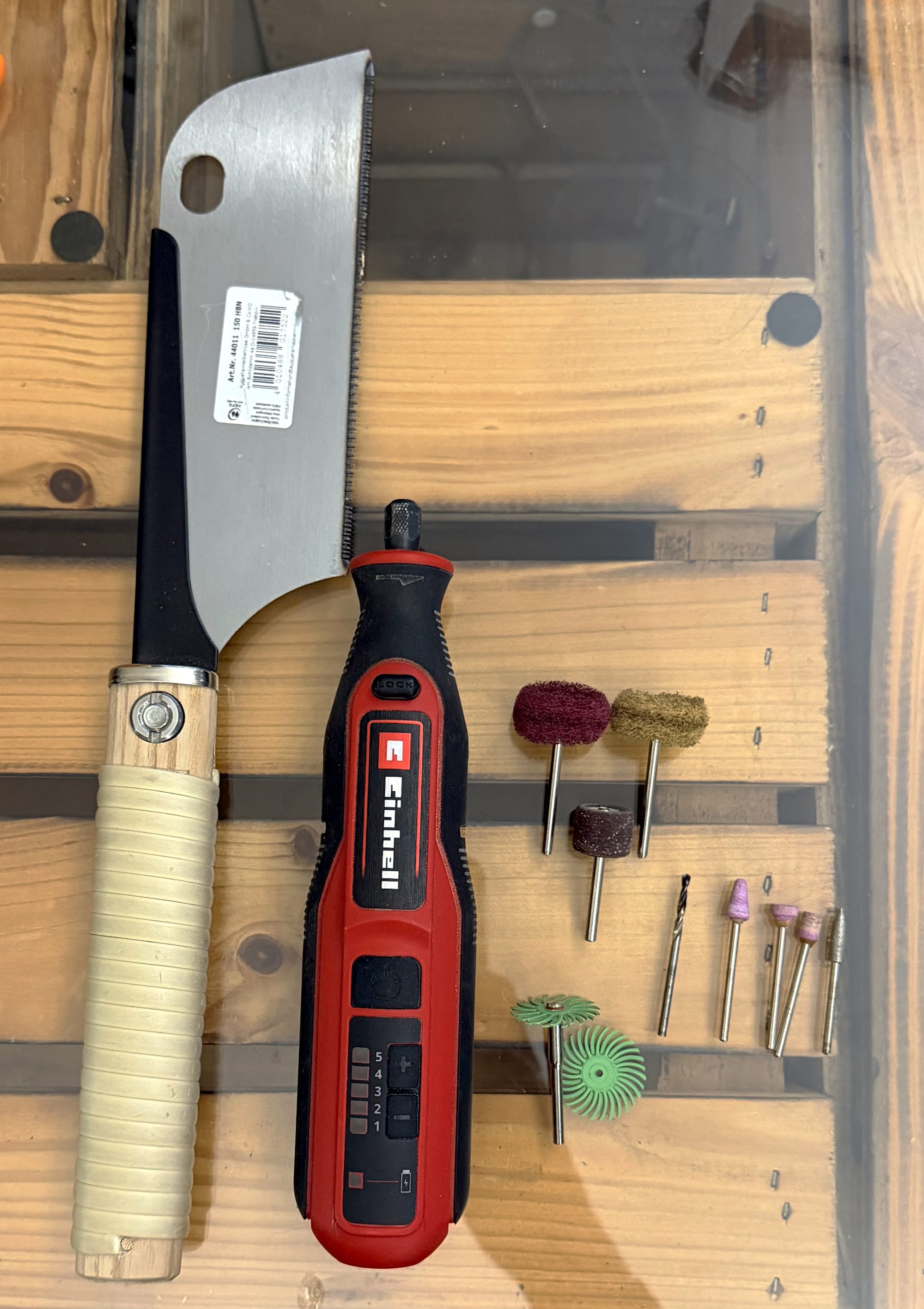
Before doing this, however, the figures must be cleaned of the remains of the two splints, any areas not completely reached by the milling machine, loose wood fibres and wood dust. For this, I recommend a small handy saw and a Dremel with attachments of various grit sizes and a drill attachment:
To apply the clear varnish, I would generally recommend using an airbrush. However, I didn't have one available at the time, so I simply dipped the figures in the clear varnish and then left them to dry. To achieve as even a result as possible, I stuck the figures onto a 3D-printed holder with double-sided adhesive tape before dipping them, which held the figures at a slight angle in the air while they dripped and dried.
If you use a water-based stain to blacken the figures, the fibres may swell slightly. After drying and before applying the clear varnish, you should therefore smooth the entire surface again with the Dremel and a brush attachment.

About The Author
I work as a teacher at a secondary school in Hanover, where I teach mathematics, physics, and computer science to students in grades 5 through 13, with a particular focus on grades 8 and above. In physics, I am particularly passionate about electricity and mechanics, and I deliberately set aside more time for these topics in my lessons so that I can give my students as tangible an understanding of them as possible.
About seven years ago, I started out in the world of 3D printing with a simple FDM printer from Anycubic, without any prior experience, and soon added a resin printer. What began as experimentation quickly turned into a passion that now has a firm place in my professional and private life. At my school, I supervise a weekly club on 3D printing and 3D modeling, where students work with Fusion 360 and learn the basics of using 3D printers, and I regularly teach 3D printing with a focus on climate protection in the elective course for 8th graders.
For my own projects, I now use different machines for specific purposes: The Snapmaker Artisan is my tool for milling and laser work, the Snapmaker U1 covers most of my FDM printing, and for particularly delicate parts, I use an Elegoo Saturn 4 Ultra. I am particularly attracted to larger projects that combine several techniques—such as homemade hi-fi speakers with printed components, milled wooden parts, and electronics, or new wooden paneling for my espresso machine. However, the chessboard with matching pieces has been my most challenging project to date because it explored the limits of what can be achieved with the Artisan and the rotation module using wood.
I have been working with Fusion 360 for about six years and during that time I have acquired in-depth knowledge in the areas of design and CAM, which I not only pass on in my classes, but also in the form of my own models, which I have been selling online for fun for several years. I have been following the Snapmaker universe for a long time: I was intrigued by the Kickstarter campaign for the first device at the time, but I wasn't experienced enough for such a device myself. Years later, however, a test video for the Artisan finally convinced me because it allows me to indulge my love of woodworking and precision manufacturing in a small space.
Working with the rotation module has really shown me how complex wood actually is—from wood types and densities to hardnesses, milling cutter geometries, and cutting materials, I've spent many hours researching and still feel like I'm only scratching the surface. At the same time, the system has enabled me to fulfill a childhood dream: Even as a child, I was fascinated by carved wooden figures - such as Asian samurai - at my uncle's house, but my own attempts at carving regularly failed. With the rotation module, I can now create figures that, despite all the digital support, feel like the result of genuine craftsmanship because an enormous amount of time and care goes into their design, settings, and fine-tuning.
In my article, I deliberately address users who, like me back then, are working with wood and the rotation module for the first time and are looking for step-by-step instructions that do not require any special knowledge. Instead of repeating basics that are already well explained elsewhere, I focus on project-specific aspects, especially pitfalls in aligning the rotation axis, which initially led to unsightly edges on my figures and whose tedious troubleshooting I would like to spare others. Behind all this is my fundamental motivation: the joy of creating things, improving existing solutions, and learning something new with every project—whether it's by switching between 3D printing, laser and CNC milling, or by integrating electronics into my work.